Tools & Materials
 THE FACTS | THE FIX | THE FINISH
If leaking seals and service bills are distressing your compressor, it's time to face the fix. While air compressors can be as diverse as the individuals that use them, most models share some general characteristics and components. Whether you are inflating your tires or creating empires, eReplacementParts.com provides the parts, procedures and facts you need to fearlessly fix what fails you.
The outlet tube transfers air between the cylinder and the tank on an air compressor. The aluminum tube also helps to cool the air as it leaves the cylinder. After years of use under continual vibration, the ends of the outlet tube may begin to crack and leak.
Less than impressed with your compressor? Replacing the outlet tube may be the solution. This article will show you how to complete the repair like an expert. THE FACTS | THE FIX | THE FINISH ! DEPRESSURIZE THE AIR TANK.
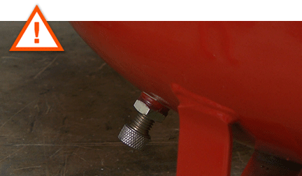
Always depressurize the tank before servicing an air compressor. To do this, open the drain valve and wait until all of the air (and pressure) has escaped.
 REMOVING THE OUTLET TUBE [top]
1. Remove the manifold cover.
Remove the retaining screw.
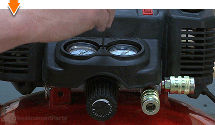
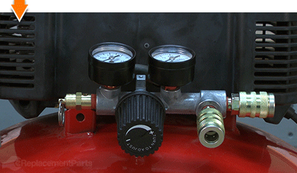
Lift the manifold cover away from the unit.
 2. Remove the pump assembly from the tank.
Remove the front retaining screw.
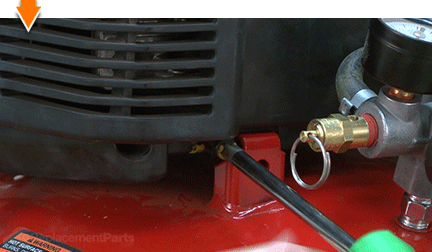
Remove the rear retaining screw.
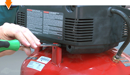
Slide the pump assembly to the side.
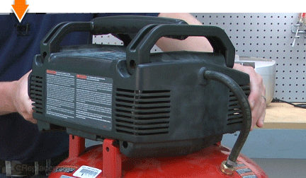
Lift the pump assembly away from the tank.
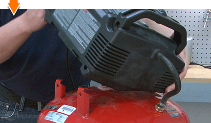
Position the pump assembly upon the isolator feet a flat work surface.
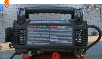 3. Remove the top handle.
Remove the two retaining screws.
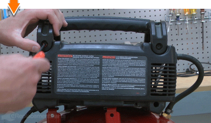
Remove the top handle from the pump housing.
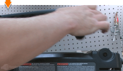 4. Remove the rear pump housing cover.
Remove the three retaining screws.
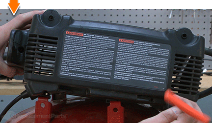
Remove the rear pump housing cover.
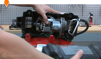 5. Remove the pump from the housing.
FIX TRIX: Make note of the original wiring configuration to simplify installation in later steps.
Use long-nosed pliers to disconnect the front wire from the field.
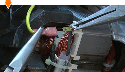
Use a flat-blade screwdriver to disconnect the ground wire from the pump.
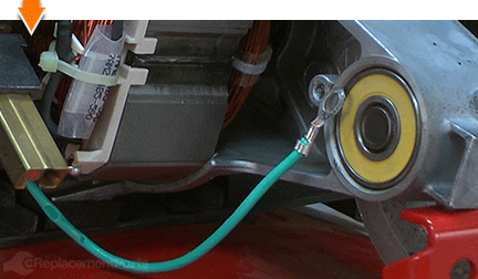
Partially extract the pump from the housing to expose the rear wire connections.
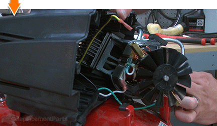
Use long-nosed pliers to disconnect the rear wire from the field.
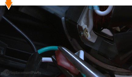
Rotate and slide the pump assembly away from the housing.
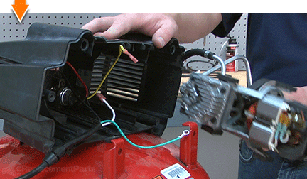 6. Disassemble the pump.
Use a small socket wrench to loosen and extract the bolts from the cylinder head.
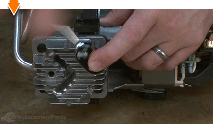
Remove the bolts from the cylinder head.
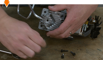
Separate the pump and internal components from the cylinder head.
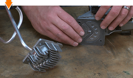
Disconnect the outlet tube from the cylinder head.
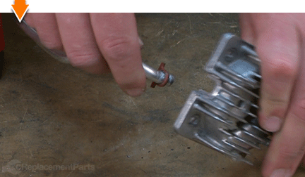
Remove the tube seal from the outlet tube.
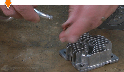 7. Remove the outlet tube from the tank hose.
SPECIFIX: Crimp-style hose clamps are designed for one-time installation only. The clamps are destroyed during the removal process, so be sure to order (or have on-hand) additional hose clamps for your specific repair project.
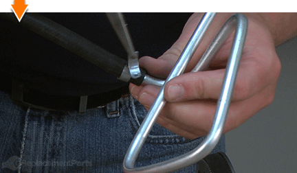
Use heavy-duty wire cutters to simultaneously cut and twist the protruding tabs of the hose clamp until the clamp breaks free.
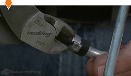
Use your fingers (or long-nosed pliers) to remove any remaining fragments of the old hose clamp.
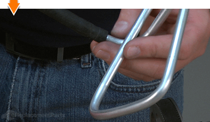
Remove the outlet tube from the tank hose.
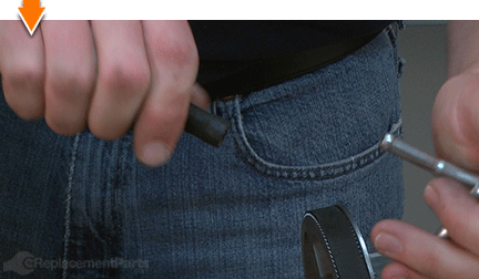 INSTALLING THE NEW OUTLET TUBE [top]
8. Install the new outlet tube.
Install a new hose clamp onto the end of the tank hose.
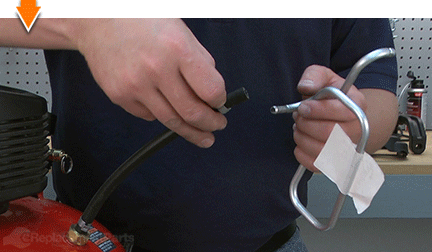
Install the new outlet tube into the tank hose.
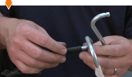
Use end-nip pliers to crimp the sides of the hose clamp and secure the hose.
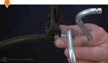
REASSEMBLING THE UNIT [top] 9. Reinstall the tube seal.
Slide the tube seal over the outlet tube.
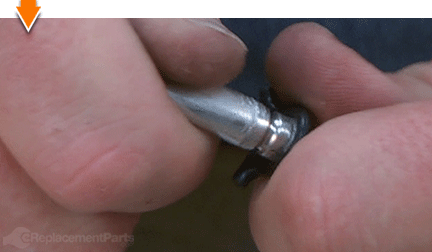
Seat the new tube seal in the groove on the outlet tube.
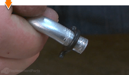 10. Reinstall the outlet tube.
Install the outlet tube (and tube seal) into the cylinder head.
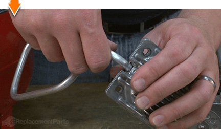 11. Rebuild the compressor pump.
Align the cylinder gasket with the valve plate assembly. (The gasket should be seated against the side of the valve plate that contains the exposed valves).
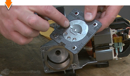
Align the valve plate assembly (and cylinder gasket) with the compressor pump. (The cylinder gasket and the exposed valves should be facing the cylinder-side of the pump.)
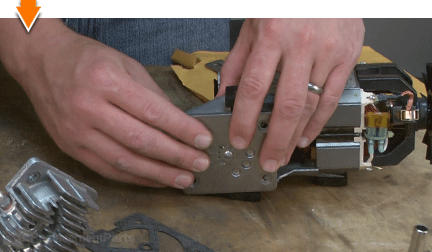
Align the head gasket with the valve plate assembly.
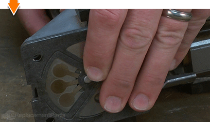
Install the cylinder head.
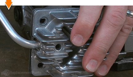
Install the head bolts.
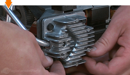
Torque the head bolts (in a crisscross pattern) to the specifications provided by the manufacturer of your specific manufacturer. (The torque specification for the Porter Cable compressor shown here is 49-55 inch-lbs.)
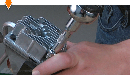 12. Reinstall the pump into the housing.
Partially install the pump into the housing.
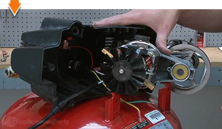
Reconnect the rear (white) wire to the field terminal.
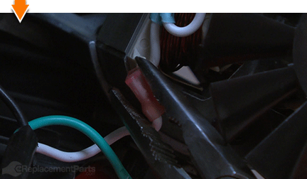
Align the feet on the compressor pump with the grooves in the housing and slide the pump fully into position within the housing.
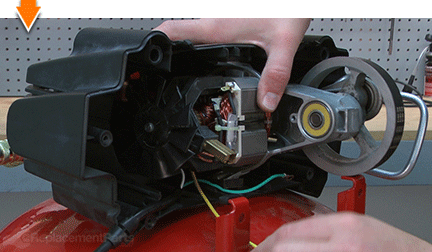
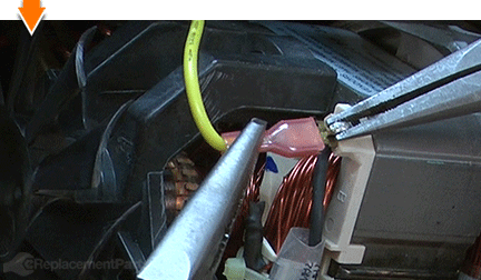
Reconnect the front (yellow) wire to the field terminal.
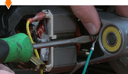
Reconnect the ground (green) wire to the pump and secure it with the screw.
 13. Reinstall the rear housing cover.
Install the rear portion of the pump housing.
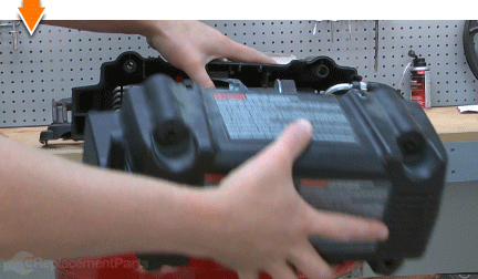
Secure the housing cover with the three screws.
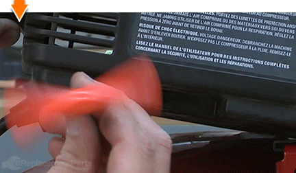 14. Reinstall the top handle.
Install the top handle to the pump housing.
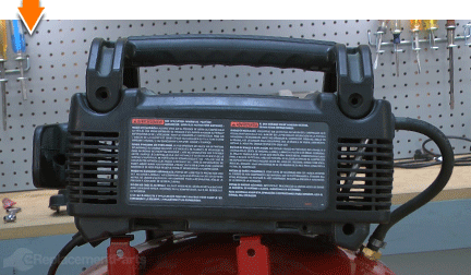
Secure the top handle with the two screws.
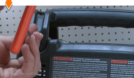 15. Reinstall the pump assembly.
Align the entire pump assembly with the compressor tank.
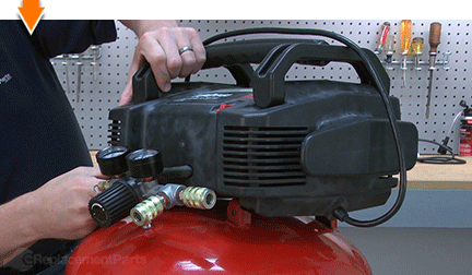
Slide the pump assembly into place upon the isolator feet.
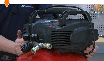
Secure the pump to the tank with the rear mounting screw.
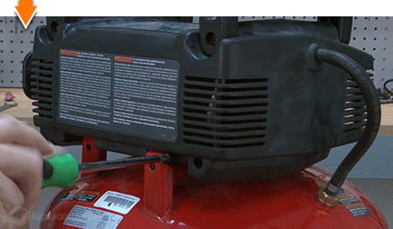
Secure the pump to the tank with the front mounting screw.
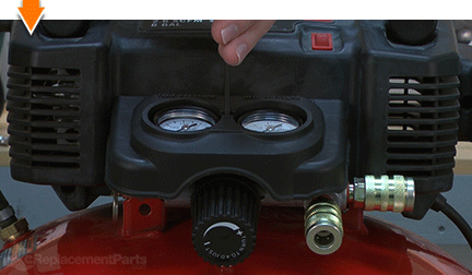
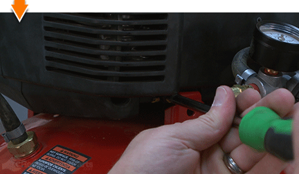 16. Reinstall the manifold cover.
Install the manifold cover.
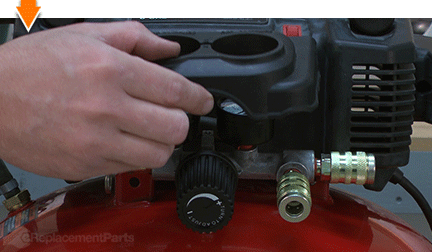
Secure the manifold cover with the screw.
 THE FACTS | THE FIX | THE FINISH
A well-maintained air compressor can mean the difference between performance under pressure, and under-pressured performance. But you don't have to empty your pockets to keep your air tank full. As you just learned, replacing an outlet tube is simpler than you think, especially when you follow our step-by-step guides. Not only did you refresh compression at a fraction of the cost of replacement; you have inflated your ability to fearlessly face the next fix, regardless of the pressure involved. Find your next fix here. [top]


