


Why Read This Article?
Finish Nailer Repair - Replacing the Driver Guide (Ridgid Part # 79004001022)
Article Breakdown
Finish Nailer Repair - Replacing the Driver Guide (Ridgid Part # 79004001022)
Video

Tools & Materials

String trimmer out of whack? It's time to face the fix. Whether you are a legendary landscaper or a weekend weed whacker, eReplacementParts.com provides the parts, procedures and facts you need to fearlessly fix what fails you.
The lower flexible drive shaft is mounted inside the lower boom housing on your trimmer attachment. Its purpose is to drive the trimmer head. Over time, the squared ends of the drive shaft can deteriorate (becoming increasingly round). Eventually, the rounded ends will fail to engage (drive) the trimmer head. It is also possible to kink (or even break) the drive shaft cable by stopping the trimmer head very rapidly. This article provides step-by-step instructions for removing and installing the lower flexible drive shaft on a Ryobi trimmer.
Let's get started.
 REMOVING THE DRIVE SHAFT [top]
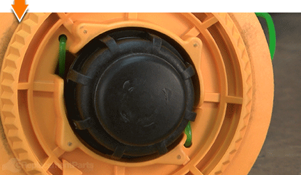
1. Remove the reel and line assembly.
REMOVING THE DRIVE SHAFT [top]
1. Remove the reel and line assembly.
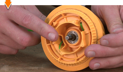
Unscrew (and remove) the bump head knob.
Remove the reel and line assembly.
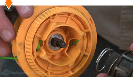
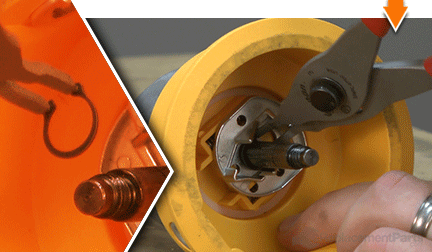
2. Remove the outer spool (trimmer head).
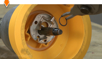
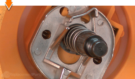
Use a pick or small screwdriver to disengage (and remove) the C-clip from the shaft.
Remove the plunger.
Remove the plunger spring.
Use split-ring pliers to disengage (and remove) the E-clip from the shaft.
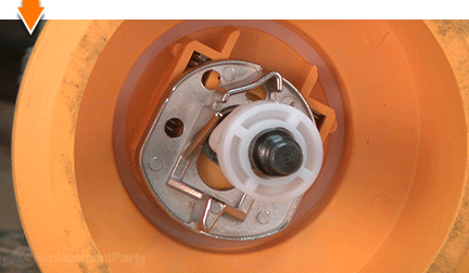
Remove the slider.
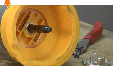
Remove the slider springs.
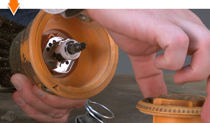
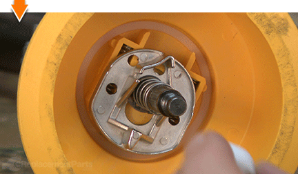
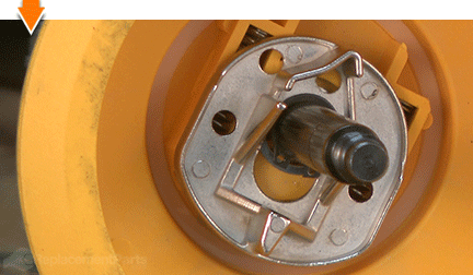
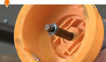
Use a pick or small screwdriver to pry the retainer away from the spool.
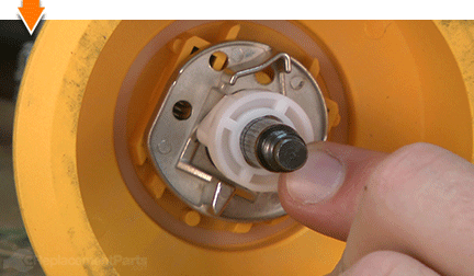
Remove the retainer from the shaft. The retainer is not reusable, so you may remove it by the simplest means necessary (including fingers, pliers, or wire cutters for particularly stubborn retainers).
Disengage the outer spool. The plastic spool is pressed onto a metal nut. To disengage it, grasp the spool firmly in one hand, and strike the center of the metal shaft with a rubber mallet (do not use a metal hammer, which will damage the shaft).
Remove the outer spool from the trimmer.
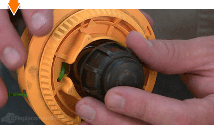
3. Remove the guard assembly.
Remove the (4) screws from the guard assembly.
Remove the guard assembly.
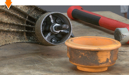
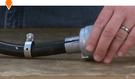
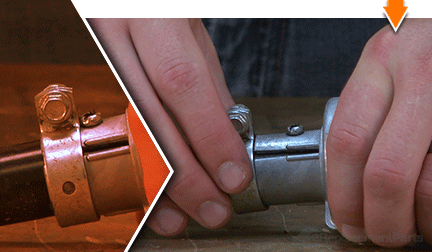
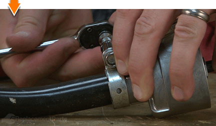
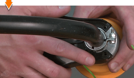
4. Remove the bushing housing assembly.
Loosen the nut on the retaining clamp.
Slide the retaining clamp away from the bushing housing assembly.
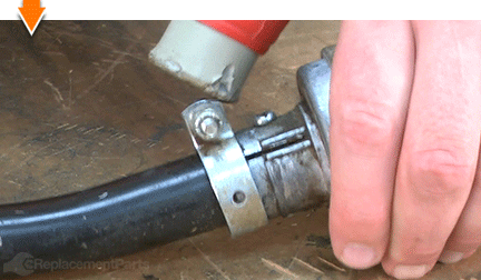
Use a Phillips screwdriver to remove the anti-rotation screw.
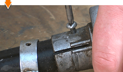
Separate the bushing housing assembly from the lower boom housing.
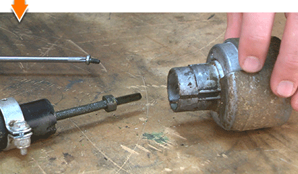
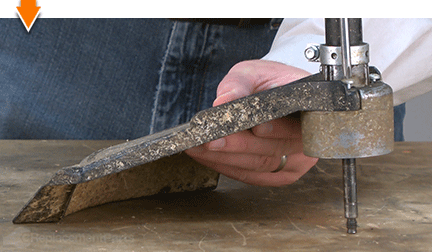
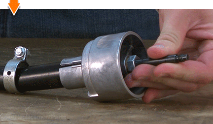
5. Remove the lower flexible drive shaft.
Slide the lower flexible drive shaft out of the lower boom housing.
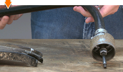
INSTALLING THE NEW DRIVE SHAFT [top] 6. Install the lower flexible drive shaft.
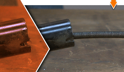
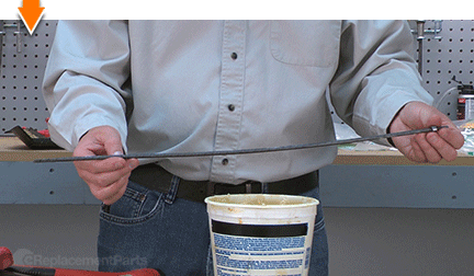
Lubricate the new flexible drive shaft with a layer of bearing/chassis grease.
Note that one end of the new drive shaft contains a metal ring. This ringed end should be installed nearest the trimmer head.
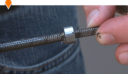
Slide the new flexible drive shaft into the lower boom housing until the stopper ring engages the stopper (preventing it from moving any further).
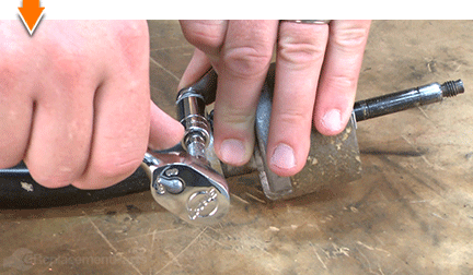
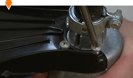
REASSEMBLING THE UNIT [top] 7. Reinstall the bushing housing assembly.
Install the retaining clamp onto the lower boom housing.
Install the bushing housing onto the lower boom housing (and drive shaft).
Rotate the spindle of the bushing housing assembly until the drive shaft engages the internal frame.
Rotate the bushing housing assembly as necessary to align the holes for the anti-rotation screw.
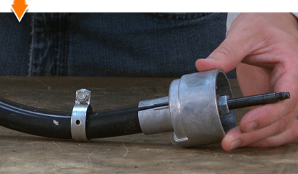
Secure the anti-rotation screw.
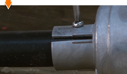
Slide the retaining clamp over the collar of the bushing housing assembly.
Secure the retaining clamp with the bolt/nut.
8. Reinstall the outer spool.
Install the outer spool onto the bushing housing assembly, ensuring that the recessed portion of the plastic spool aligns with the metal nut on the housing.
Use a rubber mallet to tap the spool into place (until the metal nut fully engages the recessed portion of the plastic).
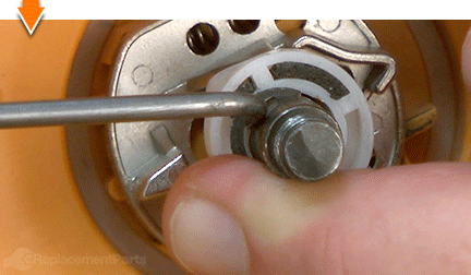
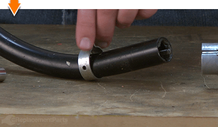
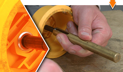
Position the spool retainer on the shaft (the beveled side of the retainer should face away from the plastic).
Securing the retainer to the shaft requires a unique (and rare) tool. To make your own tool, locate a section of hollow metal tubing (or pipe) with an inner diameter that is slightly larger than the shaft. The tube must be longer than the exposed portion of the shaft. Next, slide the metal tube/tool over the shaft and squarely against the retainer. Lastly, use a rubber mallet to tap the end of the tube/tool (pressing the retainer further along the shaft) until the retainer is seated firmly against the plastic housing.
9. Reinstall the slider.
Install the (2) slider springs into the recesses in the plastic housing.
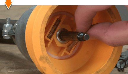
Install the slider onto the shaft.
Use split-ring pliers to install the E-clip and secure the slider.
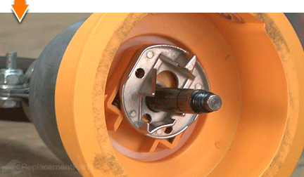
10. Reinstall the plunger.
Install the plunger spring onto the shaft.
Install the plunger onto the shaft. Note that the angled edges of the plunger should align with the angled edges of the slider.
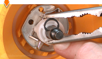
Depress the plunger against the slider until the groove for the C-clip becomes visible on the metal shaft.
Use long-nosed pliers to install the C-clip into the groove on the metal shaft (and secure the plunger).
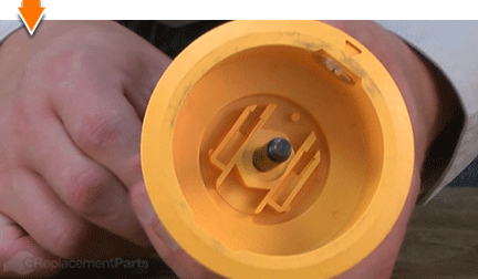
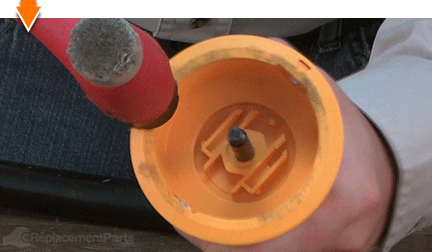
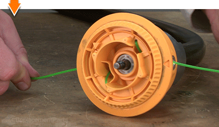
11. Reinstall the reel and line assembly.
Note that the reel assembly contains an assortment of clips (cut-outs) for holding the line in place. The V-shaped clips are designed to hold line in place for longer periods of time (such as storing pre-wound reels). The L-shaped clips are designed to TEMPORARILY hold the line in place for installation of the reel assembly.
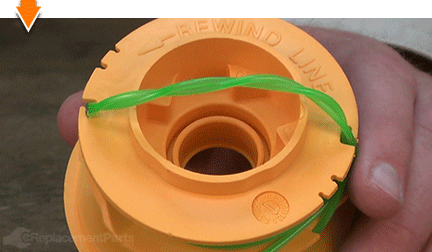
Rewind the spool until approximately 6 inches of line remains exposed for each of the two lanes. Clip the exposed line into the L-shaped channels on each side of the reel.
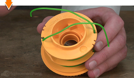
Thread the lines through the metal eyelets on the spool (one line per eyelet). The lines should pass from the inside of the spool to the outside.
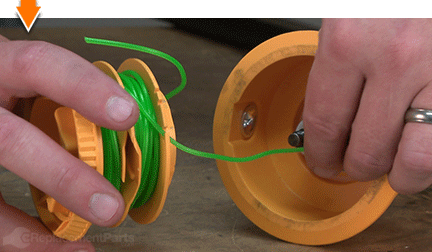
Install the reel assembly onto the shaft.
Once the reel is seated within the outer spool, gently tug on the two lines to free them from the temporary clips.
12. Reinstall the bump head knob assembly.
Install the bump head knob assembly onto the shaft.
Compress the spring while rotating the bump head knob until the internal threads engage.
Continue rotating the bump head knob until the assembly is hand-tight.
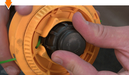
 13. Reinstall the guard assembly.
Align the tabs of the guard assembly with the notches on the bushing housing assembly.
Secure the guard assembly with the (4) screws.

You don't have to leverage your savings to level your lawns. As you just learned, repairing your own equipment is easy when you follow our step-by-step guides. Not only did you restore trimmer functionality at a fraction of the cost of replacement; you have taken the edge off of future repairs, wherever you may find them.
