Tools & Materials

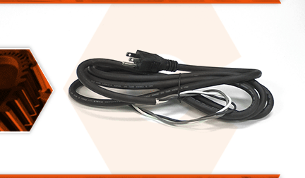
The power cord is a three-wire, sixteen-gauge cord. Power cords tend to receive lots of abuse. The cord can be cut, nicked, internally damaged, or have the prongs broken. A damaged cord should be immediately replaced to avoid electrical shock.
Let's get started.
REMOVING THE POWER CORD 1. Remove the top half of the handle.
a. Remove the (5) screws securing the top half of the handle to the lower half.
b. Use a screwdriver to separate the two halves of the handle assembly.
c. Remove the top half of the handle.
2. Remove the cord clamp.
a. Remove the (2) screws securing the cord clamp to the lower half of the handle.
b. Remove the cord clamp.
3. Remove the power cord.
a. Lift the cord and switch assembly out of the lower handle.
b. Use long-nosed pliers to disconnect the two cord wires (white and black) from the switch assembly.
c. Remove the screw securing the (green) ground wire eyelet to the motor housing.
d. Remove the power cord from the unit.
e. Remove the cord protector from the cord.
INSTALLING THE NEW POWER CORD
4. Prepare the new cord.
a. Install the cord protector onto the new power cord.
b. Using the old power cord as a guide, cut the three new cord wires to the length of the original wires.
c. Use wire strippers to strip approximately 1/4-inch of insulation from each of the new cord wires.
d. Twist the ends of each wire bundle to straighten and smooth the wire strands.
e. Install a new (slide-in style) terminal (not included) onto the end of the white cord wire and secure the connector with a crimping tool (or pliers).
f. Install a new (slide-in style) terminal (not included) onto the end of the black cord wire and secure the connector with a crimping tool (or pliers).
g. Install a new eyelet terminal onto the end of the green cord wire and secure the connector with a crimping tool.
5. Install the power cord.
a. Install the new cord assembly into the lower handle.
b. Align the cord protector with the slot in the handle.
c. Align the cord clamp with the mounting holes on the lower handle and adjust the new cord (as-necessary) until the insulation of the new cord extends beyond the clamp (toward the switch) by approximately 1/4 of an inch.
d. Secure the cord clamp with the two screws.
e. Connect the white cord wire to "connection #2" on the switch assembly.
f. Connect the black cord wire to "connection #1" on the switch assembly.
g. Secure the green ground wire (eyelet) to the inside of the motor housing using the green binder screw.
REASSEMBLING THE UNIT
6. Reinstall the top of the handle.
a. Tuck all of the wires into the lower half of the handle.
b. Install the top half of the handle.
c. Secure the top half of the handle with the (5) screws.


