Why Read This Article?
Finish Nailer Repair - Replacing the Driver Guide (Ridgid Part # 79004001022)
Article Breakdown
Finish Nailer Repair - Replacing the Driver Guide (Ridgid Part # 79004001022)
Tools & Materials

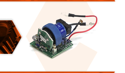
The electronic speed control switch allows you to adjust the rotational shaft speed. The circuit board contains the speed adjustment wheel and the circuitry that controls the motor's speed. If you can no longer adjust the rotary tool's speed, you will need to replace the speed control switch. This switch may also be responsible for the tool not being able to turn on. It is recommended to check the tool's power cord, switch, and brushes to verify that the speed control switch is the faulty component.
Let's get started.
REMOVING THE SPEED CONTROL SWITCH 1. Unplug the tool.
a. Disconnect the tool from its power source.
2. Remove the collet, collet nut, and collar.
a. Hold the shaft-lock button and unscrew the collet nut; then remove the collet.
b. Unscrew and remove the collar from the front of the tool's housing.
3. Remove the motor brushes.
a. Unthread the brush cap and remove the brush from the brush holder. (Do this for both brushes.)
4. Remove the hanger from the rear of the housing.
a. Pry the hanger out of the slots in the housing and remove it from the tool.
5. Open the housing.
a. Remove the five screws that fasten the two halves of the housing.
b. Pry the two halves of the housing apart.
6. Remove the motor and switch from the housing.
a. Remove the spindle lock assembly.
b. Lift the motor and switch out of the housing (as a single assembly).
c. Remove the speed control cover from the circuit board.
7. Disassemble the motor, switch, and cord wires.
a. Take note of each wire before removing them. (This will ensure the wires are reconnected in the proper place when the tool is reassembled.)
b. Disconnect the two cord wires that lead into the circuit board by removing the two screws.
c. Disconnect the (black and red) wires from the field (they are held in place with two press-in connectors).
INSTALLING THE NEW SPEED CONTROL SWITCH
8. Connect the wires.
a. Pre-route the wires on the new speed control assembly so that they are in the same position as the old assembly.
b. Wrap the red wire around the box on the circuit board.
c. Cross the black wire over the blue wire.
d. Connect the red and black wires into the receptacles on the field.
e. Connect the cord wires to the circuit board (and secure the wires with the screws).
9. Install the motor and switch assembly.
a. Install the motor assembly and new speed control switch into the housing.
b. Place the small clip on the blue wire onto the slotted post in the housing molding. Press the wire into the opening between the screw post and the mount for the rear bearing.
c. Realign the field and the armature with the housing.
d. Place the brush holders into their mounts in the housing molding. (The red should be tucked under the brush holder and into the grooves in the housing.)
RESASEMBLING THE UNIT
10. Reinstall the switch actuator bar.
a. When everything is securely tucked into the housing, install the actuator bar into the groove along the top of the housing.
11. Reinstall the speed control cover.
a. The circuit board on the speed control wheel fits into the groove on the underside of the speed control cover.
b. Connect the speed control wheel to the cover.
c. Install the speed control cover (and wheel) into the housing.
12. Reinstall the spindle lock.
a. The triangular lock button includes an embossed image of a lock. The top of the lock image should point towards the front of the tool.
b. Install the spring over the shaft of the lock button.
c. Install the lock button and spring assembly into the housing.
13. Reassemble the two halves of the housing.
a. Verify that all of the wires are properly routed throughout the lower housing.
b. Install the top half of the housing onto the bottom half.
c. Secure the housing with the five screws.
14. Reinstall the motor brushes.
a. Install the motor brush into the brush holder.
b. Secure the motor brush with the brush cap.
c. Repeat this step to install the second motor brush.
15. Reinstall the rear hanger.
a. Pry the hanger prongs apart slightly and install the hanger into the slots on the housing.
16. Reinstall the collar, collet, and collet nut.
a. Thread the collar into the end of the housing.
b. Install the collet onto the shaft.
c. Secure the collet with the collet nut.


