Why Read This Article?
Finish Nailer Repair - Replacing the Driver Guide (Ridgid Part # 79004001022)
Article Breakdown
Finish Nailer Repair - Replacing the Driver Guide (Ridgid Part # 79004001022)
Tools & Materials

Glitch in your grinder switch? It's time to face the fix. Whether you are a master mechanic or a garage-based grinder, eReplacementParts.com provides the parts, procedures and facts you need to fearlessly fix what fails you.
The "on/off" switch assembly on many Makita grinders is made up of three components: the (external) switch button, the (internal) switch lever, and the (internal) electrical switch itself. The purpose of the switch lever is to transfer the motion (of switching the grinder on and off) from the external switch button to the internal electrical switch.
Common problems with the switch lever include broken tabs (where the internal tension spring attaches) and broken ends (where the switch lever attaches to the switch button). Both of these conditions will present similar symptoms; specifically, the inability to switch the grinder on or off using the external switch button.
This article provides step-by-step instructions for removing and installing the switch lever on a Makita grinder.
Let's get started.
 REMOVING THE SWITCH LEVER [top]
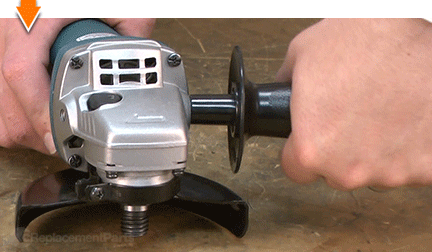
1. Remove the side handle.
Unscrew and remove the side handle from the grinder.
2. Remove the guard.
Loosen the lock-screw on the guard assembly.
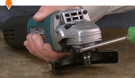
Rotate the guard assembly to disengage it from the housing.
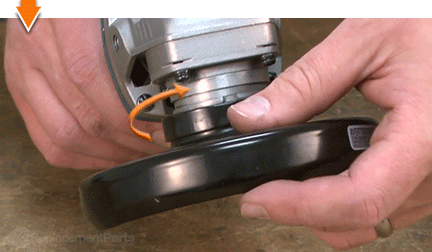
Remove the guard from the grinder.
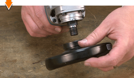
3. Remove the gear housing.
Remove the (4) screws from the gear housing.
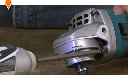
Separate the gear housing from the motor housing.
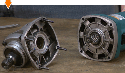
4. Remove the rear cover.
Remove the (1) screw from the rear cover.
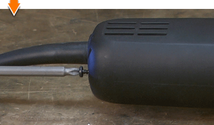
Slide the rear cover away from the motor housing.
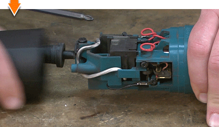
5. Disengage the motor brushes.
Use a pick to (gently) lift the brush spring from the back of the carbon motor brush.
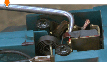
Reposition the brush spring alongside the motor brush (against the brush holder).
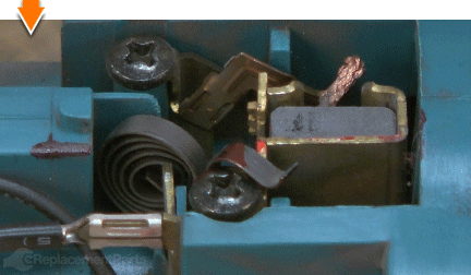
Pull (gently) on the wire lead to disengage the motor brush from the armature.
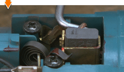
Repeat this step to disengage the second motor brush.
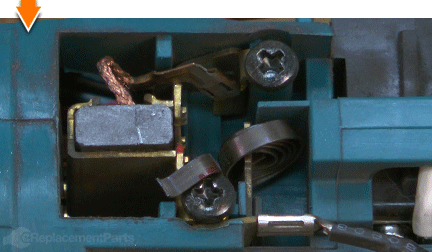
6. Remove the armature assembly.
Slide the armature assembly (which is attached to the gear housing cover) out of the motor housing.
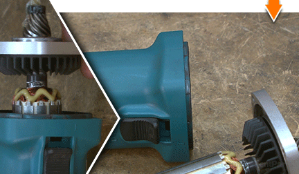
7. Remove the baffle plate.
Remove the (2) screws from the baffle plate.
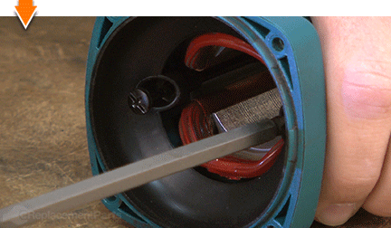
Slide the baffle plate out of the motor housing.
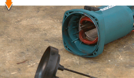
8. Remove the switch button.
Press and hold the switch button in the off position (toward the rear of the grinder).
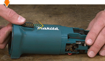
Press the switch lever toward the front of the grinder (toward the switch button) until it "clicks" and disengages the switch button.
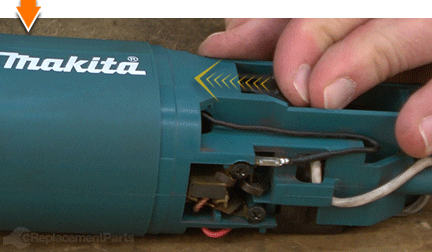
Remove the switch button from the grinder.
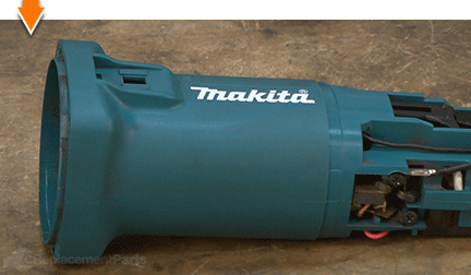
9. Remove the field from the motor housing.
While there are no actual fasteners holding the field in place, it is often wedged tightly inside the motor housing. Removing the field involves tapping the motor housing against a flat surface repeatedly until the field slides out. The following steps describe this process in general. However, the field in your grinder may slide out of its housing with less effort; so test it (by hand) between tapping sessions. And always keep one hand beneath the assembly to catch the field (in case it does slide out unexpectedly).
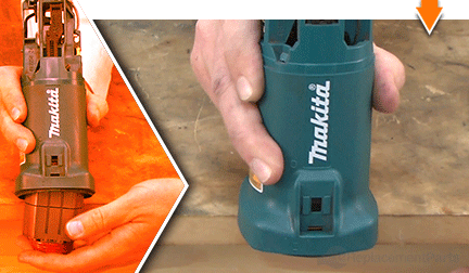
Make a note of the configuration of the four field wires. This will ensure that the wires are reinstalled correctly in later steps.
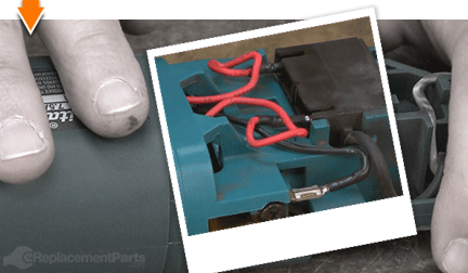
Disconnect the (2) wires from the (internal) switch (these are usually red).
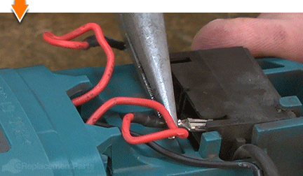
Disconnect the (2) wires from the motor brush holders (these are usually black).
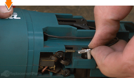
Invert and tap the motor housing assembly against your work bench.
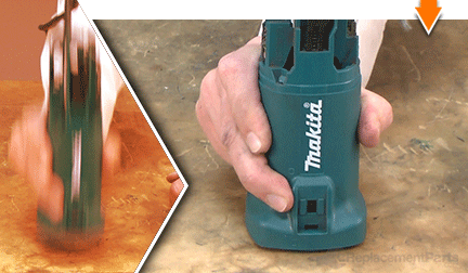
Continue tapping the motor housing until the field slides flush with the housing.
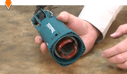
Move to the EDGE of the work bench; tap the edge of the motor housing against the edge of the work bench. (Be careful to avoid hitting the field directly against the surface.)
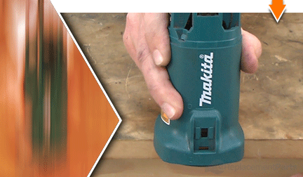
Continue tapping the motor housing against the edge of the work bench until the field moves freely.
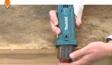
Remove the field from the motor housing assembly.
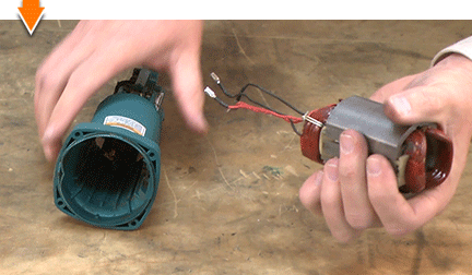
10. Remove the switch lever.
Use long-nosed pliers to disengage the switch lever from the (internal) switch button and lift the lever partially out of the motor housing.
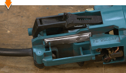
Slide the switch lever approximately halfway out of the motor housing.
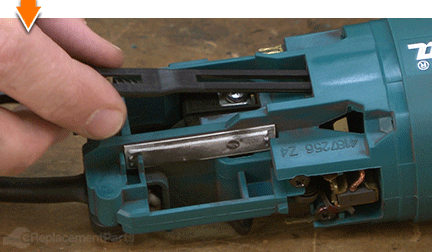
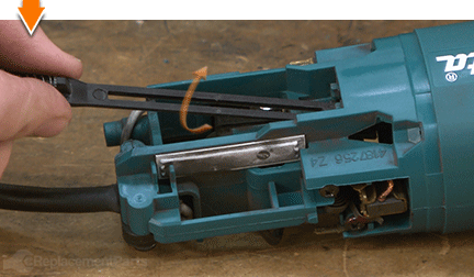
When resistance is felt, rotate (twist) the switch lever approximately 180 degrees and slide it the rest of the way out of the motor housing.
INSTALLING THE NEW SWITCH LEVER [top] 11. Transfer the spring.
Use long-nosed pliers to remove the spring from the old switch lever.
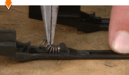
Install the spring onto the new switch lever.
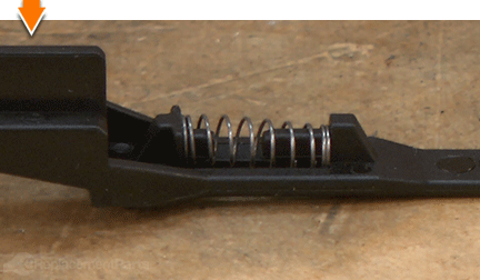
12. Install the switch lever.
Slide the new switch lever partially into the motor housing.
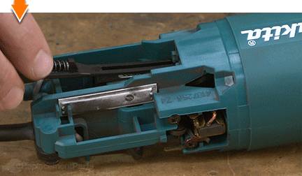
Rotate the switch lever approximately 180 degrees (to clear the tabs within the housing) and slide the switch lever the rest of the way into the housing.
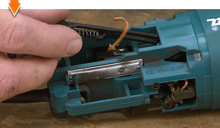
Press and release the switch lever a few times to engage the internal switch and seat the lever in the housing.
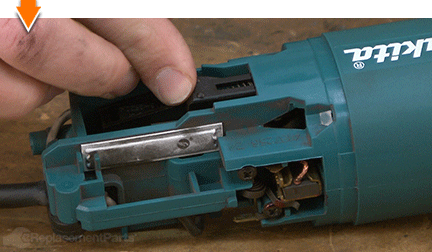
REASSEMBLING THE UNIT [top] 13. Reinstall the field.
Straighten and orient the field wires for installation. Both of the red wires (and one of the black wires) should align with the side of the housing that contains the switch. The remaining black wire should align with the brush holder on the opposite side of the housing.
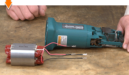
Partially install the field into the motor housing.
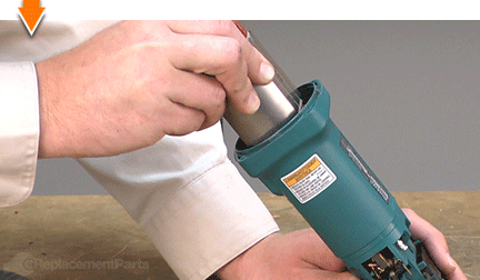
Use a large screwdriver to thread the wires through the appropriate openings in the motor housing.
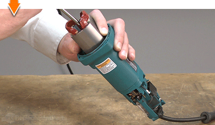
Slide the field firmly into the motor housing.
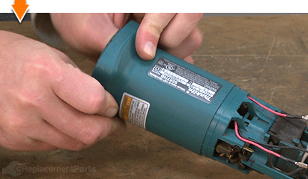
Reconnect the two (red) wires to the switch.
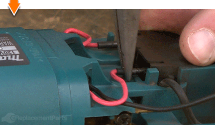
Reconnect the two (black) wires to the terminals on the two brush holders.
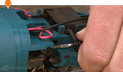
Tuck, twist, or loop the wires to eliminate slack.
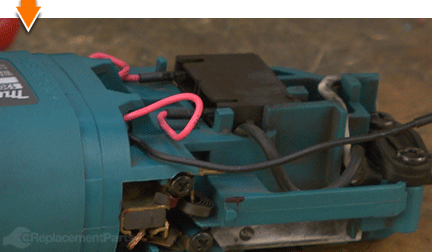
14. Reinstall the switch button.
Press and hold the switch lever (from the rear of the grinder) all the way forward (toward the front of the grinder).
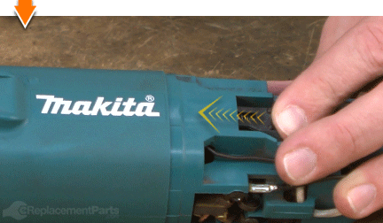
Pass the hook on the switch button through the opening on motor housing.
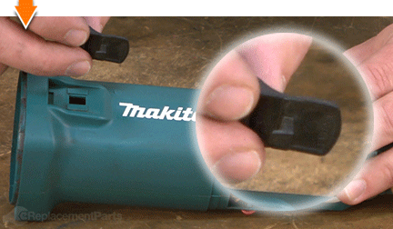
Press the switch lever onto the hook on the switch button (from inside the grinder).
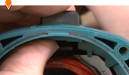
Release the switch lever (from the rear of the grinder) to engage the hook and secure the switch button.
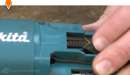
15. Reinstall the baffle plate.
Install the baffle plate into the motor housing and align the mounting holes.
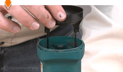
Secure the baffle plate with the (2) screws.
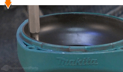
16. Reinstall the armature assembly into the motor housing.
Slide the armature assembly into the motor housing.
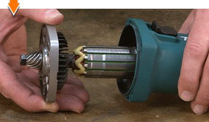
Align the gear housing cover with the motor housing.
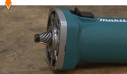
17. Reinstall the gear housing.
Install the gear housing onto the grinder (aligning the mounting holes with the gear housing cover and the motor housing).
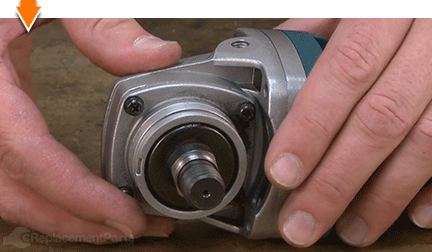
Secure the gear housing to the grinder with the (4) screws.
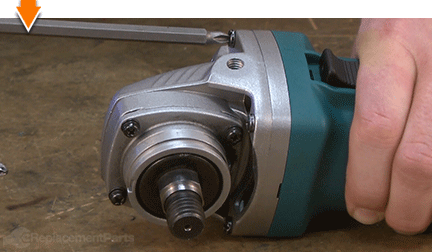
18. Re-engage the motor brushes.
Use a pick to (gently) lift the brush spring away from the brush holder.
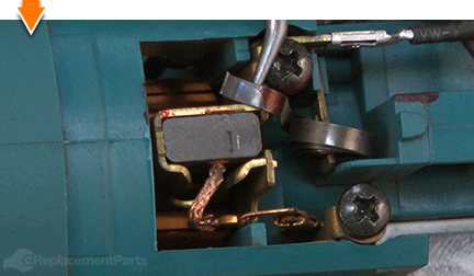
Position the brush spring against the motor brush.
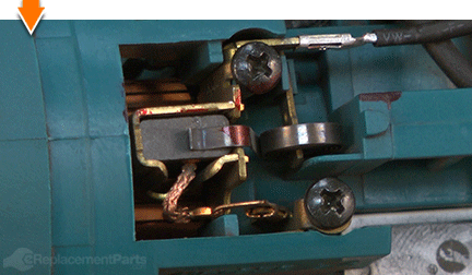
Repeat this step to engage the second motor brush.
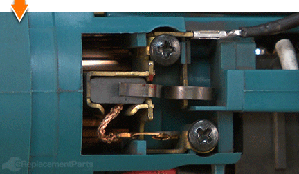
19. Reinstall the rear cover.
Visually inspect the wires for potential pinch-points and adjust/tuck the wires as necessary.
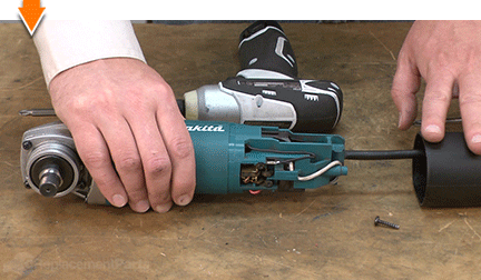
Slide the rear cover onto the motor housing.
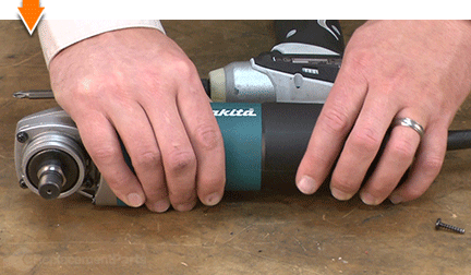
Secure the rear cover with the screw.
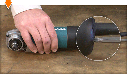
20. Reinstall the guard.
Install the guard assembly onto the grinder.
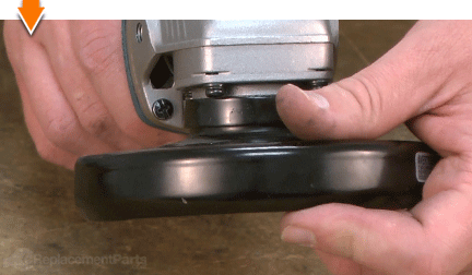
Rotate the guard assembly to engage the mounting plate.
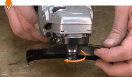
Secure the guard with the (1) screw.
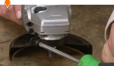
21. Reinstall the side handle.
Install the side handle onto the grinder.
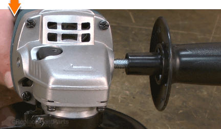
Tighten the side handle until secure.
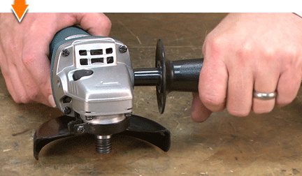

You can't place a value on a job well done, unless you did it yourself. (Which you did.) Now you can place that value back into your own pocket. (Or into your business.) Not only did you refine your grinder at a fraction of the cost of replacement; you have expanded your skills far beyond the daily grind.


