Why Read This Article?
Finish Nailer Repair - Replacing the Driver Guide (Ridgid Part # 79004001022)
Article Breakdown
Finish Nailer Repair - Replacing the Driver Guide (Ridgid Part # 79004001022)
Safety Guidelines
- Testing electrical systems is hazardous without the right training.
- Make sure that a multitester is in good condition before use. Check for damage and wear.
- Follow watts, voltage, and amperage limits for each meter to avoid damage or injury.
- Always make sure the rotary dial of a multitester is in the correct position before testing.
- Keep rotary dials in the "OFF" position between tests.
- Make sure the test leads in the correct terminals before use.
- Never test for voltage if the red test lead is in the amperage terminal.
- Only test resistance and continuity after power is terminated to the test circuit or material.
- Only touch the insulated areas of a multitester's test probes when testing to avoid shock.
- Do not test for amperage at all unless you have thorough, formal training to do so.
Definition of a Multitester Multitesters are handy tools for diagnosing electrical systems like outlets, batteries and power tool components. Multitesters get the "multi" because they combine more than one kind of electrical testing device in one. Most multitesters on the market today test for:
1. volts
2. current (amps)
3. resistance (ohms), and
4. continuity
Voltmeters test for volts, ammeters test for amps, and ohmmeters test for ohms (resistance). Multitesters are all three in one, and sometimes more. Even simple multitesters test for both AC and DC current.
Multitesters are also called multimeters, volt/ohm meters, and VOMs. These names are used interchangeably.
Multimeters are essential tools that have a rightful place in almost any toolbox. If your work, repair, or project uses electricity in any way (and it most likely does), then having a multimeter around can be critical when it really counts.
However, a user's training in, understanding of and confidence around electrical systems should determine how a multitester is used. Deciding those factors is eventually up to the user, but this article strongly recommends only using multitesters to test resistance, continuity, and simple voltage tests unless you have formal training in working with electric currents.
Testing for amps (current) is not recommended in this article because it can be dangerous, and because there will be little need (if ever) for most multitester users to test for amperage.
[Back to top]
Some Basics About Electric Current
Technical information about electric currents and multitesters gets hairy in no time, and it isn't necessary for most multimeter users. Digging into the subject deeper is a great idea if it sounds interesting to you, but having an understanding of just a few ideas and terms is just fine for most users too.
Here are a few important terms and ideas to know when working with multitesters and electric current:
Voltage
Electric current is made up of two basic things, voltage and amperage. Voltage and amperage work together to describe the wave-like behavior of electricity.
Voltage is a measurement of what is called "electric potential difference." A useful way to think about voltage, without getting technical, is to think of voltage as the force driving the electrical current.
This "force" is really the result of how electrons interact with each other in a conducting material (like metal), and how far apart electrons are from each other (theoretically) within that same conducting material.
Teachers of physics and electrical engineering often mention how difficult it is to explain exactly what voltage is in "plain English." Thinking of voltage as the "force" driving the current is inaccurate, like most comparisons and examples, but it is a functional way to understand electric currents.
Outside of that basic understanding, it is mostly important for tool users to understand the voltages at which power tools operate, and to operate them at the correct voltage. Understanding voltage also comes in handy for power tool users when testing wall outlets and batteries used to operate power tools.
Here is a shortlist of needed information about voltage:
- Voltage is a measurement of one quality of electric currents, volts.
- Voltage and volts can be thought of as "force" driving an electric current.
- Volts are expressed with a "V".
- Understanding voltage for multitester users is important for diagnosing wall outlets and batteries.
Electric current is made up of two basic things, voltage and amperage. Voltage and amperage work together to describe the wave-like behavior of electricity. Amperage measures charge. It's useful to think of amperage as describing how densely-packed or loosely-packed charged energy is as it moves across a circuit. More amperes (amps) means a "thicker" current of charged energy. This charged energy is different than voltage. When thinking of voltage as "force," voltage would be the "force" moving the "thicker" or "thinner" charges (amperage) along the path of the circuit. Voltage and amperage are like two different "flows" that intersect and affect one another to make electrical circuits possible. Measuring current (amperage) with any meter is hazardous, because a circuit must be live to test for amps. Measuring amperage is not recommended in this article and there is almost never a need to measure current for the average user of multitester.
Here is a shortlist of needed information about amperage:
- Amperage is a measurement that describes how electric charge flows through a circuit.
- Amperage can be thought of as describing how "thick" or "thin" a circuit is with charged energy, at a given point, over time.
- Amperes, or amps, are the units of amperage. Amperes are expressed with "A".
- Testing current with a multitester is hazardous and almost never needed for most multitester users.
Here is a shortlist of needed information about electrical resistance:
- Resistance measures how well or not well a material accepts electrical charge.
- Resistance is measured in ohms and is expressed as ohms, or the omega symbol.
- Testing for resistance is very safe as long as power is terminated to the testing area.
- Testing electrical resistance is a common use for most multitester users.
- Continuity tests whether or not electricity can pass between two points on a circuit.
- Continuity is a yes-or-no test and is not expressed in units.
- Testing for continuity is safe as long as power is terminated to the testing area.
- Testing electrical continuity is a common use for most mulitester users.
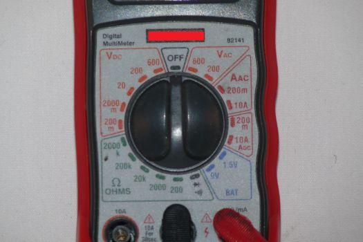
A Multitester Example Simple multitesters are small, inexpensive, and can easily meet the needs of most craftsmen, homeowners and other users. For the uses described in this article, a multitester shouldn't cost more than $50, and some are as cheap as $15. The great news is that even a small, inexpensive multitester will get the job done. Most models available will test voltage, current, resistance, and continuity in a variety of ranges and modes. Most multitesters will also do all of that for both AC and DC current. There are many different ratings, scales, functions and kinds of multitesters on the market. Paying attention to the specifications of a multitester becomes important when doing very sensitive electrical work or diagnostics. This article uses a simple, digital mutitester as an example because digital testers tend to be the most common, they are accurate enough, they can be inexpensive, and they are easy to use. The example multitester pictured below is a great example to become familiar with a multitester's parts.
 Rotary Switch:
Like most digital multitesters, the one in the above picture has a rotary switch. The rotary switch is used to select the correct setting for the kind of test being performed with the tester. Rotary switches should always be set to "OFF" when not in use. Voltage Settings:
This multitester has settings to test voltage in AC and DC currents in the orange"Vdc" and "Vac" areas to the left and right off the dial's "OFF" position. The different settings are for testing different voltage ranges. It is very important that AC or DC power is selected correctly for a test, and it is important to know the correct voltage range to test in, as it will increase the accuracy of the test. Amperage Settings:
Moving clockwise from the "Vac" section, there are two more red sections of settings for testing amperage "Aac" and "Adc." As discussed above, testing for amperage is not recommended for most users, but common multimeters will have settings for testing amperage most of the time. The best thing to do for most users is to simply make sure that the dial is never set to the amperage settings. Battery Settings:
Continuing clockwise, this multimeter's blue area has a section with two settings for testing specific batteries. Other battery testing, like testing a car's battery, would be done using the "Vdc" settings. This battery setting is a good example of a feature that may or may not come with every multitester. Ohm Settings:
This multitester's green area is for testing resistance at different ranges. The setting that is furthest counter-clockwise within the ohm settings area is the continuity test setting, and will only indicate a positive test with a "beep" when using this tester. Resistance and continuity settings are the settings that users will use the most for diagnosing power tools, machines, and other electrical systems related to their projects.
 Leads and Probes:
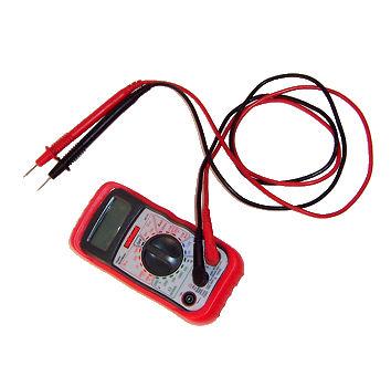
A multimeter's leads are the wires coming out of the device that end in probes. Simple multitesters usually have just two leads, one black and one red. There are several different kinds of test probes, like pointed probes and clips, but the most common are simple pointed probes.
 Jacks/Terminals:
Jacks and terminals are the same thing. They are the slots on a multimeter where the test leads are attached. Most simple multimeters have three terminals. The black probe should always be plugged into the terminal marked "Common," as a ground. The red probe should be switched to the amperage terminal for measuring amps, and then switched back to the volt/ohm terminal for everything else.
Mixing leads up is one of the most common mistakes made when using a multitester. Since this article does not recommend testing amperage anyway, it might be best just to cover the amperage terminal with a piece of tape to make sure it's never used accidently.
The other most common mistake to make with multitesters is to have the rotary switch in the wrong position for a given test. We recommend keeping the dial in the "OFF" position between uses to help ensure that the dial position is thoughtfully selected with each multimeter use.
[Back to top]
Conclusion
Multitesters are great to have when you need them. If you're using, diagnosing, or repairing a power tool, the need to have a multimeter in your toolbox has probably already made itself known.
Checking outlet voltage and battery charge are a good start for using a multimeter, but multitesters might be most useful when a tool is acting up and needs to be diagnosed on the spot.
This article only covers very basic information about multitesters. Check the "How To" articles on this website for more detailed information about specific multitester use.
Multimeters are just one helpful tool for repairs and diagnosis. Visit our Tools for Tool Repair page for tools necessary for tool repair.
[Back to top]
What we're about.


