Why Read This Article?
Finish Nailer Repair - Replacing the Driver Guide (Ridgid Part # 79004001022)
Article Breakdown
Finish Nailer Repair - Replacing the Driver Guide (Ridgid Part # 79004001022)
Tools & Materials
Safety Guidelines
 Safety glasses are recommended when working with solder.
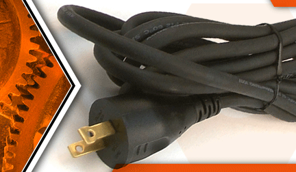

Power cord cracked? It's time to face the fix. Whether you are a master carpenter or a seasonal sander, eReplacementParts.com provides the parts, procedures and facts you need to fearlessly fix what fails you.
The cord on your sander takes a lot of abuse. As soon as damage is noticed, the cord should be replaced. Most forms of damage (such as nicks and cuts along the insulation) can by identified by visually inspecting the power cord each time the sander is used. The plug should also be inspected for missing or damaged prongs.
If you're planning to "pull the plug" on your Porter Cable random orbit sander, this article will show you how to complete the repair quickly and easily.
Let's get started.
 REMOVING THE POWER CORD [top]
1. Remove the sanding pad.
Remove the (3) screws from the sander pad.
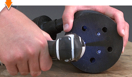
Remove the sanding pad from the sander.
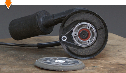
2. Remove the clutch belt.
Remove the clutch belt from the fixed pulley and the pad support pulley.
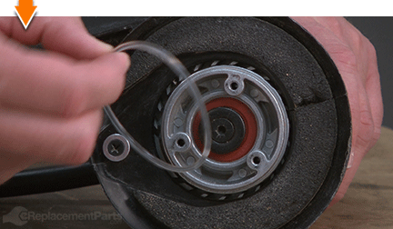
3. Remove the pad housing.
Remove the (2) screws from the pad housing.
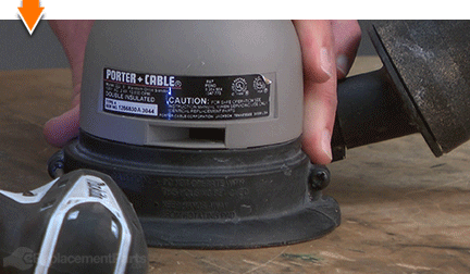
Separate the two halves of the pad housing.
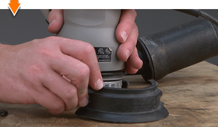
Separate the sander from the pad housing.
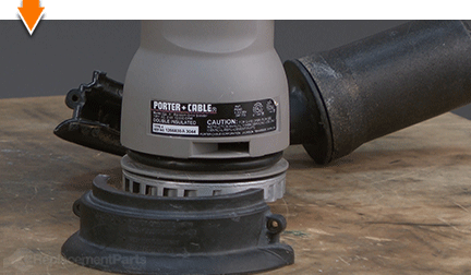
4. Remove the housing O-ring.
Use a screwdriver to pry the O-ring out of the groove in the housing.
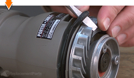
Work around the edges of the O-ring; stretching it around the pad support assembly as you move.
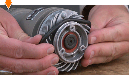
Remove the O-ring from the sander.
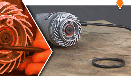
5. Remove the pad support.
Grasp the fan to prevent the pad support from rotating.
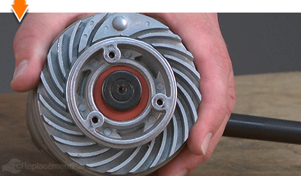
Remove the (1) screw from the pad support.
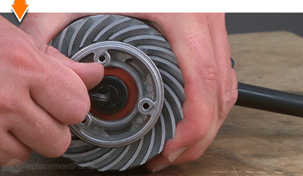
Remove the pad support (and washer) from the sander.
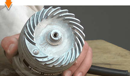
6. Remove the fan.
Slide the fan assembly off the spindle and away from the sander.
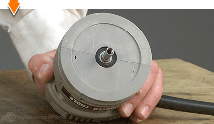
7. Split the motor housing.
Remove the (4) screws from the motor housing.
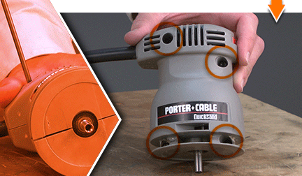
Remove the top half of the motor housing.
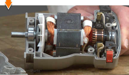
8. Remove the power cord.
Disconnect the white wire (containing the flag terminal) from the motor brush.
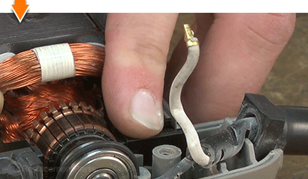
Lift the switch (and the black wire) out of the motor housing.
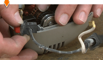
Loosen the screw that secures the black wire to the switch.
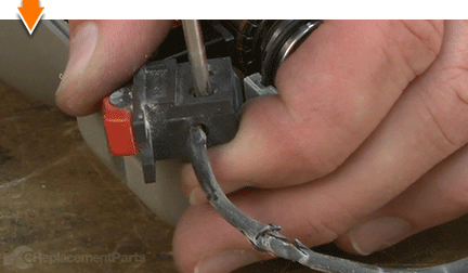
Disconnect the black wire from the switch.
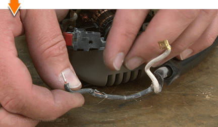
Remove the power cord from the sander.
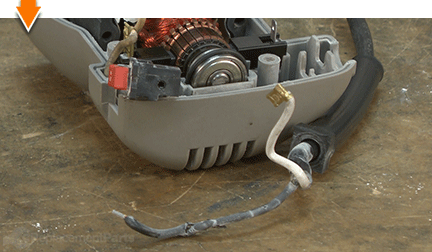
Remove the cord protector from the old power cord.
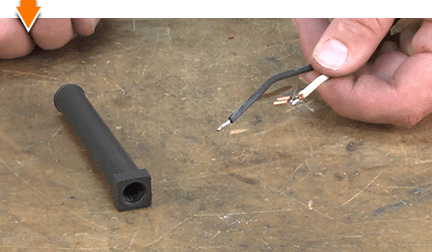
PREPARING THE NEW POWER CORD [top] 9. Cut the wires to length.
Place the new power cord beside the old cord to compare the wires.
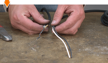
Use wire cutters to cut the wires to match the length of the original wires.
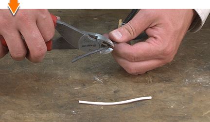
10. Install the cord protector.
Slide the cord protector onto the new power cord.
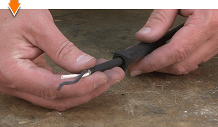
11. Prepare the wires and hardware.
Use wire strippers to strip approximately one-quarter of an inch of insulation from each of the two wires.
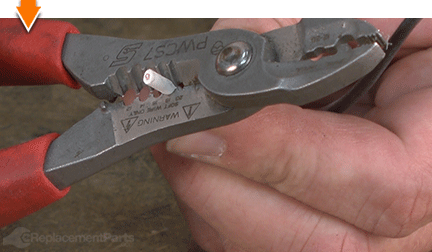
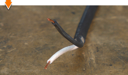
Twist the ends of the exposed wires to prepare them for installation of the terminals.
Use wire cutters to remove the extra tab from the flag terminal. (The tab is used during the manufacturing process and is not required for installation of the terminal).
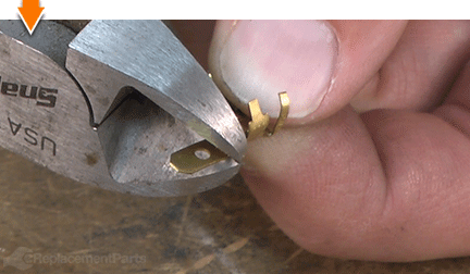
Install the flag terminal onto the WHITE wire.
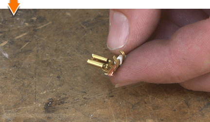
Use crimpers to secure the flag terminal to the white wire. (Flag terminals are usually installed by a machine at the factory. Because of this, they can be difficult to install by hand. However, we will be using solder to secure the flag terminal, so it is only necessary to crimp the connection sufficiently to hold it in place until the solder is applied.)
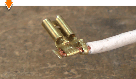
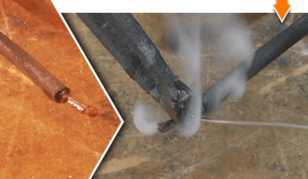
12. Solder (and tin) the wires.
Apply paste flux to both sets of wires (and to the base of the flag terminal).
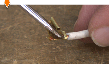
Use a soldering gun (and solder) to secure the flag terminal to the white wire.
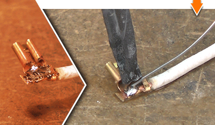
Use a soldering gun (and solder) to tin the end of the black wire.
INSTALLING THE NEW POWER CORD [top] 13. Install the power cord.
Install the black wire into the switch.
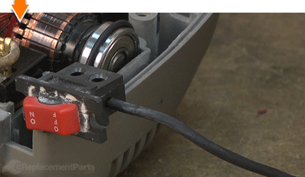
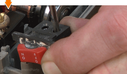
Secure the black wire to the switch with the screw.
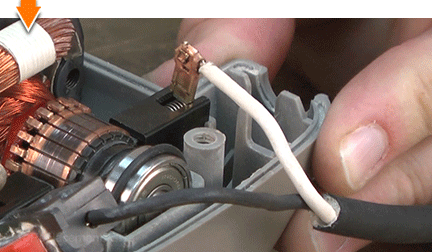
Connect the white wire (the flag terminal) to the motor brush.
REASSEMBLING THE UNIT [top] 14. Tuck the wires.
Install the switch assembly into the recess in the motor housing.
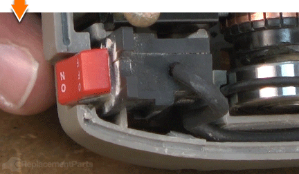
Tuck the black wire into the channel along the top of the motor housing.
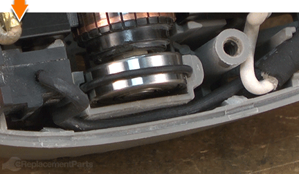
Install the cord protector into the recess in the motor housing.
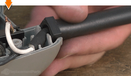
Tuck the insulated portion of the power cord (containing both sets of wires) into the channel in the motor housing.
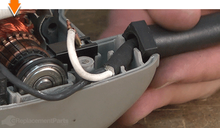
Tuck the white wire into the channel in the motor housing.
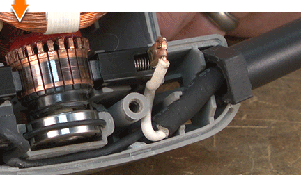
15. Reinstall the top half of the motor housing.
Install the rubber bumper into the recess on the motor housing.
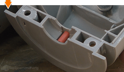
Visually inspect the wires for potential pinch-points; adjust the wires as necessary.
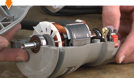
Install the top half of the motor housing.
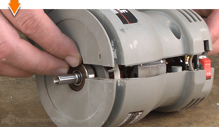
Secure the motor housing with the (4) screws.
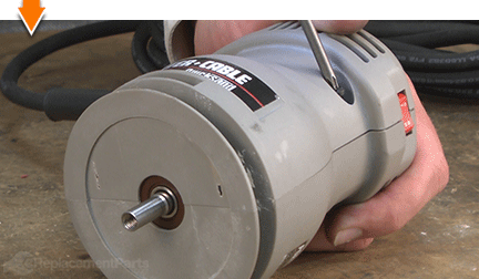
16. Reinstall the fan.
Slide the fan onto the spindle.
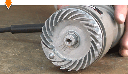
17. Reinstall the pad support.
Install the pad support onto the sander.
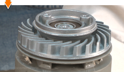
Install the washer onto the pad support. (The side with the recess should be facing away from the bearing).
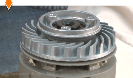
Secure the pad support with the (1) screw.
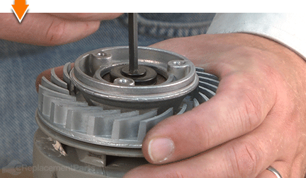
18. Reinstall the housing O-ring.
Install the housing O-ring into the groove on the motor housing.
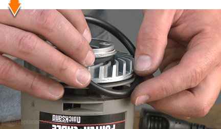
19. Reinstall the pad housing.
Install one half of the pad housing onto the sander (the seam should align with the seam on the motor housing).
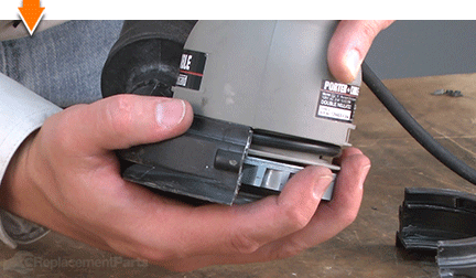
Install the second half of the pad housing onto the sander.
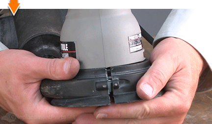
Secure the pad housing with the (2) screws.
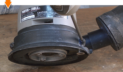
20. Reinstall the clutch belt.
Install the clutch belt onto the fixed (small) pulley.
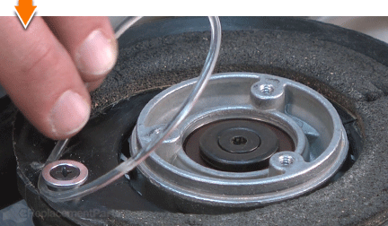
Stretch the clutch belt onto one side of the pad support.
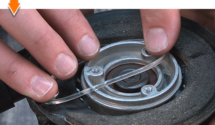
Rotate the pad support to seat the clutch belt.
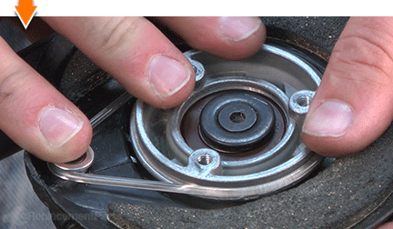
21. Reinstall the sanding pad.
For easy alignment: Pass a small screwdriver through one of the screw holes on the sander pad; then insert the end of the screwdriver into one of the holes on the pad support.
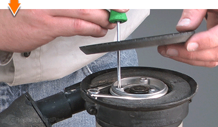
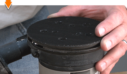
Install the sanding pad.
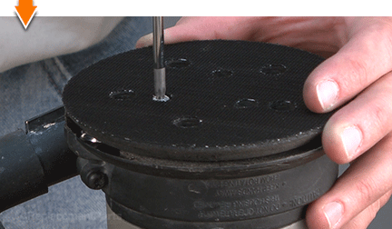
Secure the sander pad with the (3) screws.

Sanding can be a demanding task. But you don't have to rough-up your accountant to smooth-out your countertops. As you just learned, repairing your own power tools is simple when you follow our step-by-step guides. Not only did you expand sander functionality at a fraction of the cost of replacement; you have taken the edge off all future repairs.


