Why Read This Article?
Finish Nailer Repair - Replacing the Driver Guide (Ridgid Part # 79004001022)
Article Breakdown
Finish Nailer Repair - Replacing the Driver Guide (Ridgid Part # 79004001022)
Tools & Materials

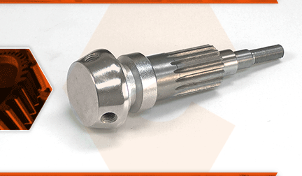
The feed shaft lowers and raises the quill on your drill press. It has the handle bars attached to it (on one side); teeth that engage with the quill (in the middle); and a slot on the opposite end (where the coil spring attaches). There are a few things that can go wrong with the feed shaft. The threads for the handle bars can strip out. The quill gearing can wear, resulting in lash (or slop) as you begin drilling a hole, and the shaft can be damaged where the return spring attaches.
Let's get started.
REMOVING THE FEED SHAFT 1. Disengage the scale seat.
a. Remove the two screws securing the seat to the body of the drill press.
b. Pivot the seat away from the coil spring assembly.
2. Remove the coil spring assembly.
a. Remove the outer nut securing the coil spring assembly.
b. Press and hold the coil spring assembly against the body of the drill press.
c. Loosen (but do not remove) the inner nut securing the coil spring (approximately 3/8" from the spring plate).
d. Use a large screwdriver to pry the coil spring assembly away from the body of the drill press. Caution: The spring will uncoil rapidly, so be sure to keep your fingers away from the assembly during this step.
e. Once the spring tension has been released, remove the inner nut from the shaft.
f. Remove the coil spring assembly from the shaft.
3. Remove the feed shaft assembly.
a. While holding the quill assembly with one hand, carefully slide the feed shaft assembly out of the drill housing.
b. Lower and remove the quill assembly from the drill press.
4. Disassemble the feed shaft.
a. Remove the scale ring from the feed shaft.
b. Use an adjustable wrench (as needed) to loosen and remove the handle bars from the feed shaft.
INSTALLING THE NEW FEED SHAFT
5. Assemble the feed shaft.
a. Install and tighten the handle bars onto the new feed shaft.
b. Install the scale ring onto the new feed shaft (the beveled portion of the ring should face the handle bars).
c. Apply grease to the gears of the new feed shaft.
6. Install the feed shaft assembly.
a. Install the quill assembly into the drill press.
b. Rotate the spindle pulley (on the top of the drill press) until the spindle shaft engages with the pulley assembly.
c. Slide the quill assembly (up) into the drill press until the gearing (on the quill) is visible through the opening for the feed shaft.
d. Carefully install the feed shaft, rotating the assembly (as necessary) to align and engage the gearing.
REASSEMBLING THE UNIT
7. Reinstall the coil spring.
a. Install the coil spring assembly onto the exposed portion of the feed shaft, aligning the center (straight) leg of the spring with the slot on the shaft.
b. Install and tighten the inner nut until there is approximately 3/8" between the nut and the spring plate.
8. Tension the coil spring.
a. Protective gloves are recommended for this step.
b. Grasp and rotate the coil spring assembly counter clockwise to add tension to the coil spring.
c. To reposition your hands, press the coil spring assembly against the body of the drill until the inner spring engages the indexing notch on the housing.
d. Continue tensioning the coil spring until the quill assembly retracts into the drill housing.
e. To test the tension of the spring: tighten the inner nut; extend the quill (using the handle bars); then release the handle bars. The quill should retract (spring) firmly and consistently back into the upper housing. If not; loosen the inner nut and increase tension on the coil spring. Repeat this step until the coil spring is ideally tensioned for your specific application.
f. Once the coil spring is ideally tensioned, tighten the inner nut and re-test the quill. The goal here is to tighten the inner nut sufficiently to prevent the coil spring from pulling away from the housing (and uncoiling); but loose enough to allow the quill assembly to glide (extend and retract) freely. Repeat this step until the inner nut is ideally tensioned for your specific application.
g. Use adjustable pliers to hold the inner nut (to prevent it from rotating further).
h. Install and tighten the outer nut to secure the coil spring.
9. Engage the scale seat.
a. Pivot the scale seat back into position against the body of the drill press and align the mounting holes.
b. Secure the scale seat with the screws.


