


Why Read This Article?
Finish Nailer Repair - Replacing the Driver Guide (Ridgid Part # 79004001022)
Article Breakdown
Finish Nailer Repair - Replacing the Driver Guide (Ridgid Part # 79004001022)
Video

Tools & Materials
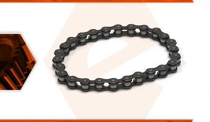
Your planer's feed rollers are driven by chains and sprockets. One chain connects the gearbox to the outfeed roller, and the other chain connects the outfeed roller to the infeed roller. The chains can wear and stretch over time. This can cause them to skip on the sprockets. Rarely, a chain will even break.
Let's get started.
REMOVING THE DRIVE CHAIN(S) 1. Remove the side covers.
a. Remove the two screws securing the left (side) cover to the planer.
b. Pivot the upper portion of the side cover toward the planer and lift the side cover until its bottom portion clears the rail on the frame.
c. Remove the left (side) cover from the planer.
d. Repeat this step to remove the right (side) cover from the planer.
2. Raise the cutter head.
a. Use the crank handle to raise the planer's cutter head to its highest position.
3. Tilt the planer.
a. Carefully tilt (and lay) the planer on its front.
4. Remove the chain cover.
a. Use a short (stubby) Phillip's screwdriver to remove the two screws securing the chain cover to the housing.
b. Remove the chain cover from the unit.
5. Remove the chain(s). Note: The two chains are identical, and the three visible sprockets are identical. The fourth sprocket (behind the visible sprocket on the outfeed roller) is the only one that is different (it has a slightly taller hub than the other three sprockets). As such, the process for removing/replacing the chains is the same, regardless of which chain you are replacing. Just be sure to keep track of the inner sprocket (if replacing the inner chain), so that it may be installed in the correct position. The following steps outline the procedure for replacing the inner chain. If you are only replacing the outer chain, simply skip to the installation instructions after removing it.
a. Use snap-ring pliers to remove the retaining rings from the outer two sprockets (three, if replacing the inner chain).
b. Slowly and simultaneously slide the two outer sprockets (and the outer chain) away from the roller assemblies.
c. Remove the sprockets from the outer chain. (If you are replacing only the outer chain, skip to the installation steps now.)
d. Slowly and simultaneously slide the two inner sprockets (and the inner chain) away from the roller assemblies.
e. Remove the sprockets from the inner chain.
INSTALLING THE NEW DRIVE CHAIN(S)
6. Install the inner chain.
a. Install the new chain onto the two inner sprockets. Both hub stems should face the same direction (toward the rollers). The left-hand sprocket (the one that attaches to the outfeed roller) contains the taller hub.
b. Align the hub key of the right-hand sprocket (the one that attaches to the motor) with key way on the roller and press the sprocket partially onto the roller shaft.
c. Align the left-hand sprocket with the shaft of the outfeed roller and rotate the outfeed roller until the hub key (on the sprocket) aligns with the keyway on the roller shaft.
d. Press the both sprockets firmly onto the roller shafts.
e. Secure the two (inner) sprockets with the retaining rings.
7. Install the outer chain.
a. Install the new chain onto the two outer sprockets. Both hub stems should face the same direction (toward the rollers).
b. Align the hub key of the left-hand sprocket (the one that attaches to the outfeed roller) with key way on the roller shaft and press the sprocket partially onto the shaft.
c. Align the right-hand sprocket with the shaft of the infeed roller and rotate the infeed roller until the hub key (on the sprocket) aligns with the keyway on the roller shaft.
d. Press both sprockets firmly onto the roller shafts.
e. Secure the two (outer) sprockets with the retaining rings.
REASSEMBLING THE UNIT
8. Reinstall the chain cover.
a. Install the chain cover.
b. Secure the chain cover with the two screws.
9. Reinstall the side covers.
a. Install the top portion of the left (side) cover.
b. Lift the side cover until the bottom portion clears the rail on the frame.
c. Press the side cover down until the bottom portion seats behind the frame rail.
d. Secure the left (side) cover with the two screws.
e. Repeat this step to install the right (side) cover.
