


Why Read This Article?
Finish Nailer Repair - Replacing the Driver Guide (Ridgid Part # 79004001022)
Article Breakdown
Finish Nailer Repair - Replacing the Driver Guide (Ridgid Part # 79004001022)
Video

Tools & Materials

If spinning wheels and service bills are grinding at your nerves, it's time to face the fix. Whether you are a grinding professional or a seasonal grinder, eReplacementParts.com provides the parts, procedures and facts you need to fearlessly fix what fails you.
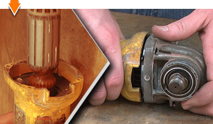
The bearing cup is a protective rubber cap that fits securely over the rear armature bearing. Its purpose is to center the bearing in the field case, and to absorb the motion of the spinning armature. Typically, the bearing cup will not fail on its own. More often, it is a casualty of neighboring component failures (usually the bearing).
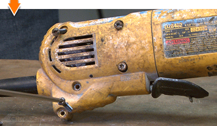
Replacing the bearing cup is very easy to do. It's also very inexpensive compared to the components it protects. As such, the bearing cup should be inspected (or replaced) whenever the grinder is disassembled for service. This article will show you how to easily and economically replace the bearing cup on a DeWALT D28402 angle grinder. Let's get started.
 REMOVING THE BEARING CUP [top]
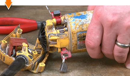
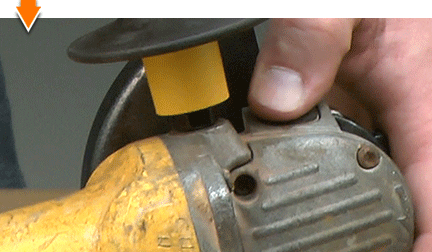
1. Remove the side handle.
REMOVING THE BEARING CUP [top]
1. Remove the side handle.
Unscrew and detach the side handle from the grinder.

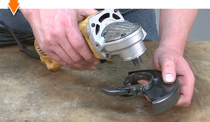
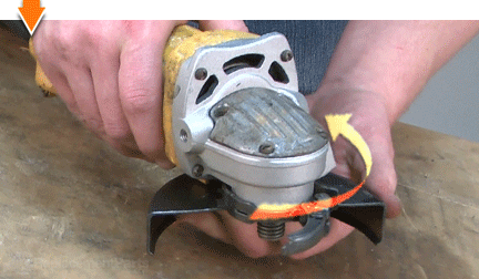
2. Remove the guard.
Raise the guard latch.
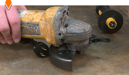
Rotate the guard until the lugs disengage.
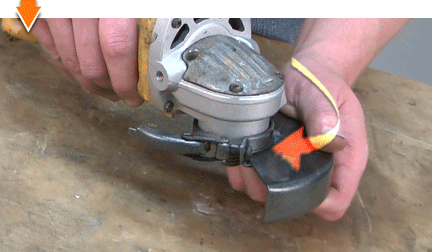
Remove the guard from the grinder.
3. Remove the top half of the handle assembly.
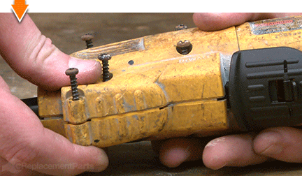
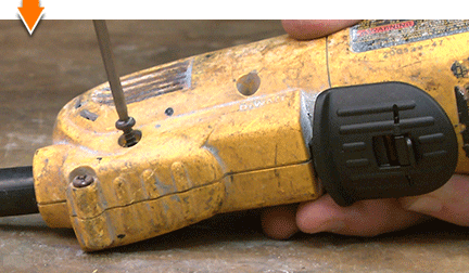
Remove the (5) retaining screws.
Remove the top half of the handle assembly.
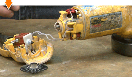
4. Separate the handle from the field case.
Remove the paddle assembly.
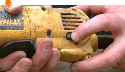
Remove the lock-on button assembly.
Separate the handle from the field case.
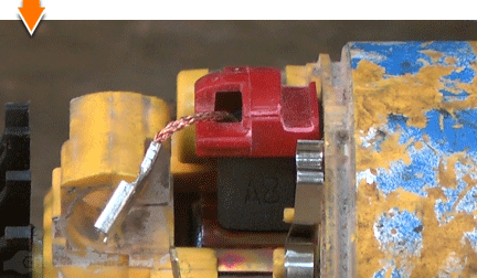
5. Disengage the motor brushes.
Use long-nosed pliers to detach the brush wire from the terminal.
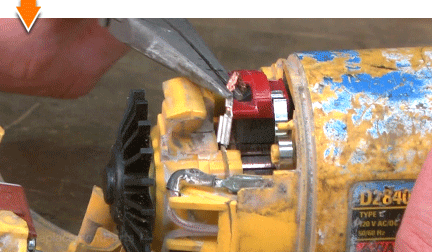
Use long-nosed pliers to lift the brush spring away from the brush arm.
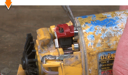
Lift (rotate) the brush arm assembly away from the armature.
Repeat this step to disengage the second motor brush (on the opposite side of the grinder).
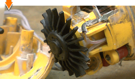
6. Remove the separator/fan.
Press and hold the spindle-lock button (on the gear case) to prevent the motor from spinning.
The separator fan is REVERSE-THREADED; rotate the fan in a CLOCKWISE direction to loosen it.
Remove the fan from the armature shaft.
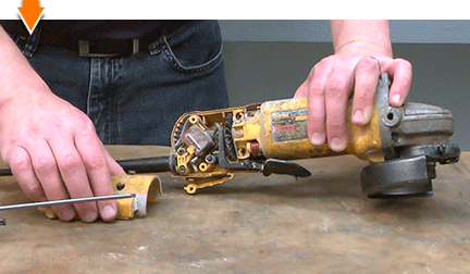
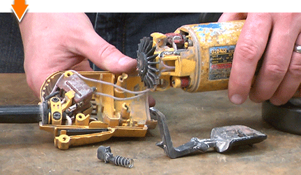
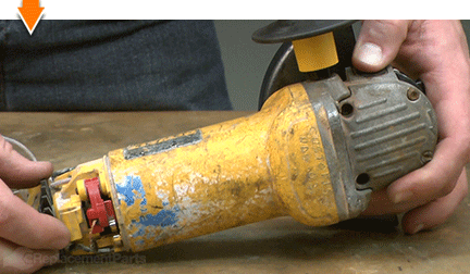
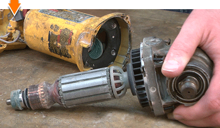
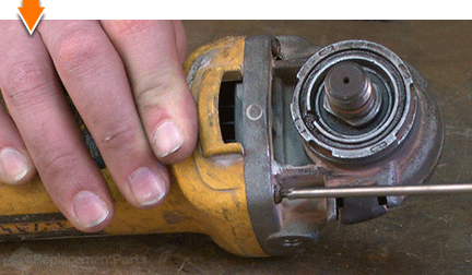
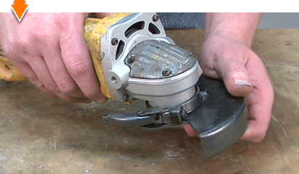
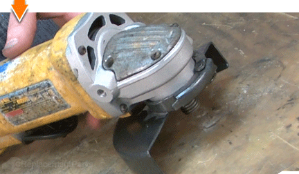
7. Remove the gear case assembly.
Remove the (4) gear case retaining screws.
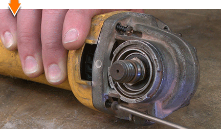
Using a flat-blade screwdriver, gently pry the gear case assembly away from the field case.
Slide the gear case assembly (and armature) out of the field case.
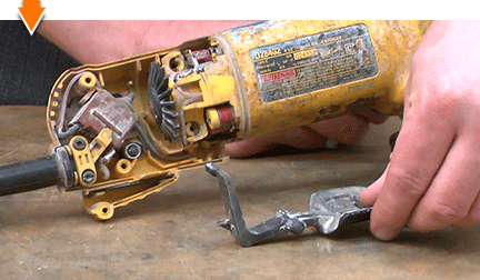
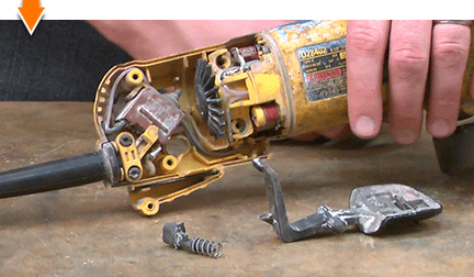
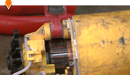
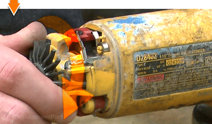
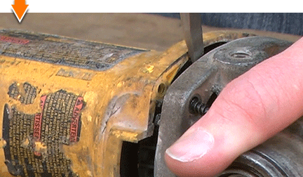
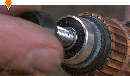
8. Remove the bearing cup.
Remove the rubber cup (cover) from the armature bearing.
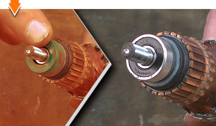
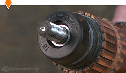
INSTALLING THE NEW BEARING CUP [top] 9. Install the bearing cup.
Install the new bearing cup onto the bearing.
Rotate the bearing a few times and verify that the cup is evenly positioned.
REASSEMBLING THE UNIT [top] 10. Reinstall the gear case (and armature) assembly into the field case.
Slide the gear case (and armature) assembly into the field case.
Secure the gear case with the screws.
11. Reinstall the separator/fan.
Press and hold the spindle-lock button (on the gear case) to prevent the motor from spinning.
The separator/fan is REVERSE-THREADED; rotate the fan in a COUNTERCLOCKWISE direction to secure it to the armature.
12. Re-engage the motor brushes.
Lower (rotate) the brush arm assembly into position above the armature.
Use long-nosed pliers to re-engage the brush spring.
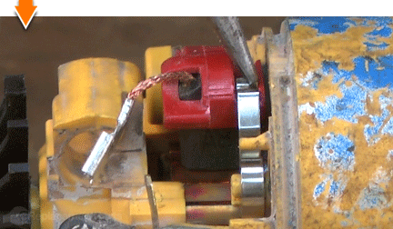
Reattach the brush wire.
Repeat this step to re-engage the second motor brush (on the opposite side of the grinder).
13. Reattach the handle assembly to the field case.
Connect the lower half of the handle to the field case (when properly aligned, the two components should snap together).
Tuck the wires into the designated channels inside the handle.
14. Reinstall the lock-on button.
One side of the lock-on button contains a small tab. This tab should be installed facing the armature.
Install the lock-on button into the handle.
15. Reinstall the paddle assembly.
Install the paddle assembly into the handle; ensure that the tail is positioned above the switch button, and the fulcrum is seated within the recess in the handle.
16. Reinstall the top half of the handle assembly.
Partially install the top half of the handle assembly.
Align the posts (on the paddle and the lock-on button) with the recesses in the top of the handle.
Before securing the handle with the screws, test the paddle and the lock-on button for proper functionality.
Secure the handle with the screws.
17. Reinstall the guard.
Install the guard onto the grinder.
Press and rotate the guard to engage the lugs.
Lower the latch to secure the guard.
 18. Reinstall the side handle.
Thread the side handle onto the gear case assembly.

You can't place a value on a job well done, unless you did it yourself. (Which you did.) Now you can place that value back into your own pocket. (Or into your business.) Not only did you refine your grinder at a fraction of the cost of replacement; you have expanded your skills far beyond the daily grind.
