


Why Read This Article?
Finish Nailer Repair - Replacing the Driver Guide (Ridgid Part # 79004001022)
Article Breakdown
Finish Nailer Repair - Replacing the Driver Guide (Ridgid Part # 79004001022)
Video

Tools & Materials
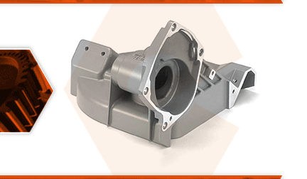
Your porta-band's gear case is a central component that serves several important functions: It supports the bearings, gears, and spindle that drive the blade pulley. It houses the blade pulley and acts as a blade guard. The back of the switch handle attaches to it. The rear blade guide and the bumper also attach to it.
There are a number of problems that can occur, which would require the case to be replaced. The total failure of a drivetrain bearing or gear can cause damage to the gear case. A seized bearing may spin in the housing, causing the opening of the housing to wear over-sized. This results in a sloppy fit, and play for a new bearing. A seized bearing or a failed gear can cause the housing to crack.
If the saw is dropped, the gear case can be cracked, or a portion might be broken off, especially around the blade pulley and the rear switch handle. The threads -- where the rear blade guide and the bumper attach -- can be stripped-out, making it impossible to firmly attach these pieces to the saw.
Let's get started.
REMOVING THE GEAR CASE ASSEMBLY 1. Remove the rear handle assembly.
a. Remove the screws securing the top half of the rear handle assembly.
b. Lift the top half of the rear handle assembly away from the lower half.
c. Remove the four screws securing the lower half of the rear handle to the saw.
d. Carefully move the lower half of the rear handle assembly away from the saw housing.
2. Remove the blade guard.
a. Remove the (2) screws securing the blade guard to the saw.
b. Remove the blade guard.
3. Remove the gear case assembly.
a. Remove the (4) screws securing the gear case to the motor.
b. Use a rubber mallet to tap the gear case assembly away from the motor.
4. Remove the old grease.
a. Use a small scraper to scrape away as much of the old grease as possible from both the motor and the gear case assembly.
5. Remove the intermediate gear from the gear case.
a. Grasp the intermediate gear with one hand while rotating the blade pulley slowly with your other hand.
b. Rock the intermediate gear back and forth in the gear case while simultaneously extracting (pulling) the gear from the gear case.
c. Use a small scraper and/or brake parts cleaner to remove as much of the old grease as possible from the intermediate gear assembly.
d. Use a small scraper to remove as much of the old grease as possible from the gear case assembly and motor housing.
6. Remove the blade pulley.
a. Remove the (3) screws securing the blade pulley cover.
b. Remove the blade pulley cover.
c. Use retaining-ring pliers to remove the retaining ring from the blade pulley axle.
d. Remove the nylon washer from the blade pulley axle.
e. Lift the blade pulley away from the gear case assembly.
7. Remove the drive sprocket and chain.
a. Lift the drive sprocket and chain assembly away from the gear case.
b. Remove the second nylon washer from the blade pulley axle.
8. Remove the worm gear assembly from the gear case.
a. Remove the (2) screws securing the worm gear assembly (and bearing) to the gear case.
b. Use a screwdriver to carefully pry the worm gear assembly away from the gear case.
c. Remove the worm gear assembly from the gear case.
d. Use a scraper and/or brake parts cleaner to thoroughly remove the old grease from the worm gear assembly and bearing.
9. Remove the inner bearing from the gear case.
a. Use reverse-grip pliers to remove the (inner) intermediate shaft bearing from the gear case housing. If you do not have specialty pliers or pullers, consider replacing this bearing entirely on your new gear case assembly.
10. Remove the blade pulley shaft.
a. Grasp and hold the base of the blade pulley shaft with adjustable pliers.
b. Use a screwdriver to remove the screw securing the blade pulley shaft to the gear case assembly.
c. Remove the blade pulley shaft from the gear case.
11. Remove the bumper.
a. Remove the (3) screws securing the bumper to the gear case.
b. Remove the bumper from the gear case.
12. Remove the rear blade guide assembly.
a. Remove the (2) screws securing the rear blade guide to the gear case.
b. Remove the rear blade guide assembly from the gear case.
13. Remove the nameplate.
a. Use long-nosed pliers to remove the two (small) screws securing the nameplate to the gear case assembly.
b. Remove the nameplate from the gear case.
INSTALLING THE NEW GEAR CASE ASSEMBLY
Note: Many of the mounting holes on your new gear case assembly are not (yet) threaded. The self-tapping fasteners (originally used by the manufacturer) will be easier to install with an impact driver (though using an impact driver is not required).
14. Install the nameplate.
a. Align the nameplate with the mounting holes on the new gear case.
b. Use long-nosed pliers to tighten the (2) screws and secure the nameplate to the new gear case. (These screws are self-tapping; and initial installation often requires a bit of patience and perseverance.)
15. Install the rear blade guide assembly.
a. Align the rear blade guide assembly with the mounting holes on the new gear case.
b. Partially install the inner screw to hold the blade guide in position.
c. Install and tighten the outer screw.
d. Tighten the inner screw to secure the rear blade guide assembly to the gear case.
16. Install the bumper.
a. Install the bumper onto the new gear case assembly.
b. Secure the bumper to the gear case with the (3) screws.
17. Install the blade pulley shaft.
a. Install the blade pulley shaft onto the new gear case assembly.
b. Install and partially tighten the screw securing the blade pulley shaft to the gear case assembly.
c. Grasp and hold the base of the blade pulley shaft with adjustable pliers.
d. Use a torque wrench to tighten the mounting screw to (between) 95-135 inch-LBS.
18. Install the worm gear assembly.
a. Liberally pack the worm gear bearings, gears and shaft with fresh grease (totaling approximately 1.5 ounces of new grease).
b. Install the worm gear assembly into the new gear case. (The assembly will be secured in later steps.)
19. Install the intermediate shaft.
a. Liberally pack the intermediate shaft, bearings, and gears with fresh grease.
b. Install the intermediate shaft assembly into the new gear case. (It may be necessary to slightly retract the worm gear assembly to ensure that the intermediate shaft seats inside the case).
c. Secure the worm gear assembly with the screws.
d. Liberally pack the gear case (above the intermediate shaft assembly) with fresh grease.
REASSEMBLING THE UNIT
20. Reconnect the two halves of the saw.
a. Install the gear case assembly onto the motor assembly.
b. Secure the gear case assembly to the motor assembly with the screws.
21. Reinstall the blade guard.
a. Install the blade guard onto the saw.
b. Note that two types of screws are used to secure the blade guard (one contains a lock washer; the other contains a milled shoulder). The screw containing the milled shoulder should be installed on the motor-side of the saw. The screw containing the lock washer should be installed on the gear case.
c. Secure the blade guard with the screws (as noted above).
22. Reinstall the blade pulley.
a. Install the first nylon washer onto the blade pulley shaft.
b. Install the drive gear and chain assembly onto the blade pulley shaft.
c. Install the blade pulley.
d. Install the second nylon washer onto the blade pulley shaft (over the blade pulley).
e. Install the retaining ring.
23. Reinstall the blade pulley cover.
a. Install the blade pully cover.
b. Secure the blade pulley cover with the three screws.
24. Reinstall the rear handle.
a. Install the lower half of the rear handle.
b. Secure the lower half of the rear handle with the screws.
c. Tuck any exposed wires into the channels on the lower handle assembly.
d. Verify that the switch is properly aligned with the lower handle assembly.
e. Install the top half of the rear handle.
f. Secure the top half of the rear handle with the screws.
