


Why Read This Article?
Finish Nailer Repair - Replacing the Driver Guide (Ridgid Part # 79004001022)
Article Breakdown
Finish Nailer Repair - Replacing the Driver Guide (Ridgid Part # 79004001022)
Video
Tools & Materials

Burnt armature grinding at your nerves? It's time to face the fix. Whether you are a master mechanic or a garage-based grinder, eReplacementParts.com provides the parts, procedures and facts you need to fearlessly fix what fails you.
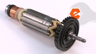
The armature is one of the main components inside your grinder's electric motor. It consists of the wire windings, the commutator, the cooling fan and the bearings. Armatures commonly fail due to a variety of problems that arise over time: When the windings overheat, it's not uncommon to see burning on the wires themselves, or on the insulation around the wires.
A worn or damaged commutator is another common problem. Often, the commutator bar (or more than one bar) will break away from the commutator. The cooling fan is also susceptible to damage from metal and other debris that may enter the grinder. It's not uncommon to find several (or all) of the cooling fins torn away from the fan. When this occurs, the motor will quickly overheat, causing additional damage to the windings.
Lastly, the armature bearings will deteriorate over time, and they will need to be replaced. This article provides step-by-step instructions for removing and installing the armature assembly on a Makita angle grinder.
Let's get started.
 REMOVING THE ARMATURE [top]
1. Remove the side handle.
REMOVING THE ARMATURE [top]
1. Remove the side handle.
Unscrew and remove the side handle from the grinder.
2. Remove the guard.
Loosen the lock-screw on the guard assembly.
Rotate the guard assembly to disengage it from the housing.
Remove the guard from the grinder.
3. Remove the gear housing.
Remove the (4) screws from the gear housing.
Separate the gear housing from the motor housing.
4. Remove the rear cover.
Remove the (1) screw from the rear cover.
Slide the rear cover away from the motor housing.
5. Disengage the motor brushes.
Use a pick to (gently) lift the brush spring from the back of the carbon motor brush.
Reposition the brush spring alongside the motor brush (against the brush holder).
Pull (gently) on the wire lead to disengage the motor brush from the armature.
Repeat this step to disengage the second motor brush.
6. Remove the armature assembly.
Slide the armature assembly (which is attached to the gear housing cover) out of the motor housing.
7. Remove the drive gear.
Grasp the armature to prevent it from rotating.
Use a wrench to remove the drive gear retaining nut.
Remove the drive gear from the armature spindle.
8. Remove the gear housing cover from the armature.
Position the gear housing cover against the open jaws of a bench vise. Adjust the vise so that the gear housing cover rests squarely against the (top) of the vise jaws. The cooling fan (on the armature assembly) should be centered between (but not in contact with) the jaws.
Use a rubber mallet to tap the armature shaft (repeatedly) until the armature assembly breaks free from the bearing (inside the gear housing cover).
Remove the gear housing cover from the armature assembly.
INSTALLING THE NEW ARMATURE [top] 9. Install the gear housing cover (and bearing).
Slide the gear housing cover (and bearing) onto the shaft of the new armature assembly.
Locate a socket that has the same diameter as the inner race of the bearing.
Position the socket squarely against the bearing.
Tap the socket with a rubber mallet to press the bearing (and the gear housing cover) onto the armature shaft.
REASSEMBLING THE UNIT [top] 10. Reinstall the drive gear.
Install the drive gear onto the armature spindle.
Secure the drive gear with the nut.
11. Reinstall the armature assembly into the motor housing.
Slide the armature assembly into the motor housing.
Align the gear housing cover with the motor housing.
12. Reinstall the gear housing.
Install the gear housing onto the grinder (aligning the mounting holes with the gear housing cover and the motor housing).
Secure the gear housing to the grinder with the (4) screws.
13. Re-engage the motor brushes.
Use a pick to (gently) lift the brush spring away from the brush holder.
Position the brush spring against the motor brush.
Repeat this step to engage the second motor brush.
14. Reinstall the rear cover.
Visually inspect the wires for potential pinch-points and adjust/tuck the wires as necessary.
Slide the rear cover onto the motor housing.
Secure the rear cover with the screw.
15. Reinstall the guard.
Install the guard assembly onto the grinder.
Rotate the guard assembly to engage the mounting plate.
Secure the guard with the (1) screw.
16. Reinstall the side handle.
Install the side handle onto the grinder.
Tighten the side handle until secure.

You can't place a value on a job well done, unless you did it yourself. (Which you did.) Now you can place that value back into your own pocket. (Or into your business.) Not only did you refine your grinder at a fraction of the cost of replacement; you have expanded your skills far beyond the daily grind.
