


Why Read This Article?
Finish Nailer Repair - Replacing the Driver Guide (Ridgid Part # 79004001022)
Article Breakdown
Finish Nailer Repair - Replacing the Driver Guide (Ridgid Part # 79004001022)
Video
Tools & Materials

If falling leaves and a broken blower are threatening to bury you beneath a pile of debt and debris, it's time to face the fix. Whether you are a seasonal garden enthusiast or a seasoned landscape professional, eReplacementParts.com provides the parts, procedures and facts you need to fearlessly fix what fails you.
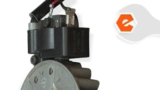
The ignition module is responsible for generating electricity, which it then transfers to the spark plug. Without electricity, there can be no spark, and hence; no internal combustion. While there are various reasons for ignition module failure, the primary symptoms usually manifest in the form of extreme difficulty starting your blower, and eventually, a no-start condition.
This article provides step-by-step instructions for removing and installing the ignition module on a Ryobi handheld trimmer.
Let's get started.
 REMOVING THE IGNITION MODULE [top]
1. Remove the blower tube.
REMOVING THE IGNITION MODULE [top]
1. Remove the blower tube.
Twist and pull the tube away from the blower.
 2. Remove the side housing from the blower.
Remove the two screws securing the base extension to the housing.
Remove the base extension from the housing.
Remove the screws securing the side housing.
Separate the side housing from the main assembly.
 3. (Preparing to) Remove the fan.
FIX TRIX: You will discover that rotating the nut causes the fan and the motor shaft to rotate concurrently, precluding your ability to loosen the nut from the shaft. This obstacle can be overcome by removing the spark plug and binding the cylinder with a short length of starter rope.
 4. Remove the spark plug.
Using a spark plug boot puller tool, remove the spark plug boot.
Use a ratchet wrench to unscrew the spark plug; remove the spark plug.
 5. Bind the cylinder.
Thread a short length of starter rope into the cylinder to fill the space between the top of the piston and the top of the cylinder. This will prevent the piston (and motor) from moving during removal of the fan.
 6. Remove the fan.
Remove the nut holding the fan on the motor shaft; remove the washer.
Remove the fan.
 7. Remove the air filter cover and side cover.
Unscrew the retaining bolt and pull gently to remove the air filter cover.
Remove the retaining screws and remove the side cover from the blower.
 8. Remove the throttle cable from the carburetor.
Retract the throttle arm slightly to create slack in the throttle cable; remove the cable from the carburetor assembly.
 9. Remove the remaining half of housing from the engine assembly.
Remove the screws securing the housing to the engine.
Separate the housing from the engine assembly. Note the position of the spacer tube and washer on the engine shaft, as these may slide readily from the assembly.
 10. Remove the ignition module wires.
Using long-nosed pliers, disconnect the (black) ignition wire from the wire terminal.
Extract the screw connecting the (red) ignition wire to the top of the ignition module.
Disconnect the red wire from the module.
11. Remove the ignition module.
Remove the screw securing the ignition module to the engine.
Remove the ignition coil from the engine.
INSTALLING THE NEW IGNITION MODULE [top] 12. Install the new ignition module.
SPECIFIX: There are two magnets located on the side of the flywheel, which must be aligned with the base of the ignition module. Rotate the flywheel to adjust the position of the magnets.
Set the ignition module in place ensuring alignment with the magnets on the flywheel.
Install (but DO NOT TIGHTEN fully) the mounting screw removed in step 11.
13. Install the red ignition wire.
Insert (but DO NOT TIGHTEN fully) the second screw through the eyelet of the red ignition wire and through the ignition module into the engine.
14. Set the gap between the ignition module and the flywheel.
FIX TRIX: An ignition gapping gauge is recommended to accurately complete this step. However, if you do not have an ignition gapping gauge (measuring .014 inches or .35mm) it is generally acceptable to use one (1) thick business card or two (2) thin business cards as substitutes.
Pull the ignition module away from the magnets on the flywheel and insert the gapping gauge between them.
With the gauge still in place, securely tighten both of the mounting screws.
Remove the gapping gauge.
15. Reinstall the black ignition wire.
Using long-nosed pliers, reinstall the black ignition wire to the wire terminal on the ignition module.
REASSEMBLING THE UNIT [top] 16. Reinstall the engine housing.
Side the washer over the motor shaft and seat it into the flywheel recess.
Align the housing above the motor shaft and slide it into position. (Ensure that the spark plug connector is not obstructed or pinched by the housing.)
Secure the housing to the engine with the screws.
Slide the spacer tube onto the motor shaft.
 17. Reinstall the motor housing (side cover).
Install the motor housing and secure it with the screws removed earlier.
 18. Reinstall the throttle cable.
Retract the throttle arm slightly and using long-nosed pliers install the throttle cable into the attachment recess.