Why Read This Article?
Finish Nailer Repair - Replacing the Driver Guide (Ridgid Part # 79004001022)
Article Breakdown
Finish Nailer Repair - Replacing the Driver Guide (Ridgid Part # 79004001022)
Tools & Materials

If broken parts and faulty starts are grinding on your nerves, it's time to face the fix. Whether you are a grinding pro or seasonal grinder, eReplacementParts.com provides the parts, procedures and facts you need to fearlessly fix what fails you.
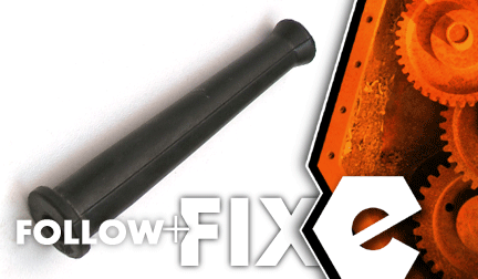
The cord protector (aka, "strain relief"), protects the cord wires from pulling out of the grinder. Over time, the cord protector can develop cracks and abrasions. It can also break when severely impacted or bent into extreme positions. The cord protector should be replaced as soon as damage is detected. Replacing the component is easy to do. And this simple repair will protect your grinder's cord (and your wallet) from sustaining further damage.
This article provides step-by-step instructions for replacing the cord protector on a DeWALT D28402 angle grinder. Let's get started.
 REMOVING THE CORD PROTECTOR [top]
1. Remove the top half of the handle assembly.
Remove the (5) retaining screws.
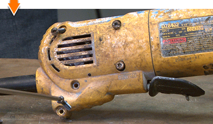
Remove the top half of the handle assembly.
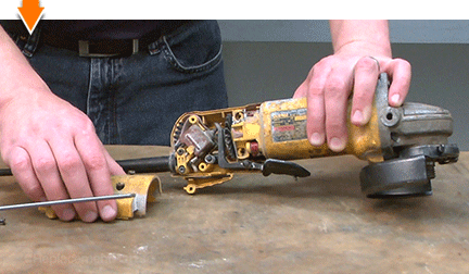
2. Separate the handle from the field case.
Remove the paddle assembly.
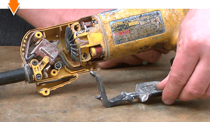
Remove the lock-on button assembly.
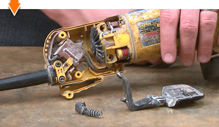
Separate the rear housing from the front.
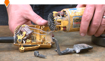
3. Remove the cord clamp.
Remove the clamp retaining screws.
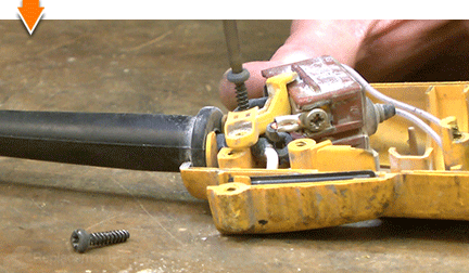
Remove the cord clamp.
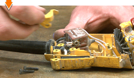
4. Remove the power cord.
Lift the cord and switch assembly out of the handle.
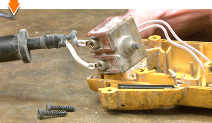
Remove the screws connecting the cord to the switch.
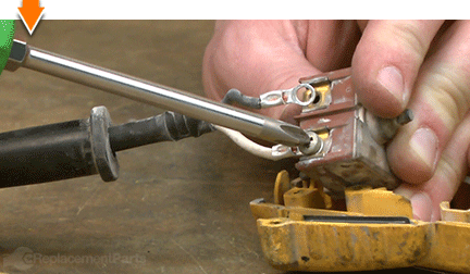
Remove the power cord from the grinder.
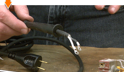
5. Remove the cord protector.
Slide the cord protector off the power cord.
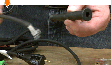
INSTALLING THE NEW CORD PROTECTOR [top] 6. Install the cord protector.
Slide the new cord protector (strain relief) onto the power cord.
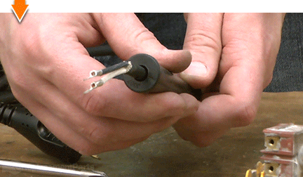
REASSEMBLING THE UNIT [top] 7. Connect the power cord to the switch.
Align the eyelets with the mounting holes on the switch.
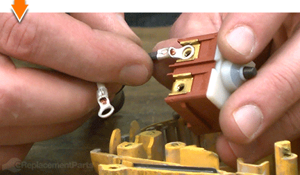
Secure the connections with the screws.
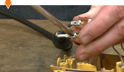
8. Reinstall the cord / switch assembly into the handle.
Reinstall the switch into the handle.
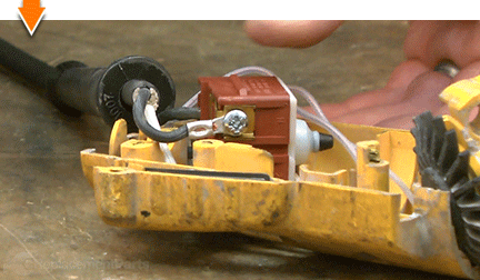
Reinstall the cord and cord protector into the handle.
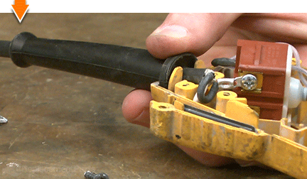
Tuck the cord wires into the handle.
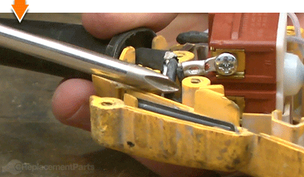
Reinstall the cord clamp.
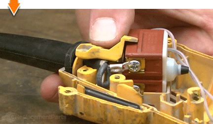
Secure the cord clamp (and switch) with the screws.
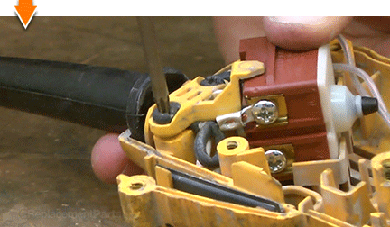
9. Reconnect the handle assembly to the field case.
Partially connect the lower half of the handle assembly to the field case.
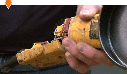
Tuck the wires into the designated slots and channels on the assembly.
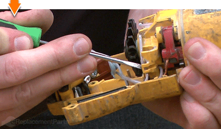
Connect the lower half of the handle to the field case (manipulate the two components until they snap into place).
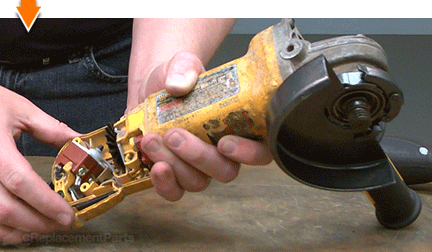
10. Reinstall the lock-on button.
One side of the lock-on button contains a small tab. This tab should be installed facing the armature.
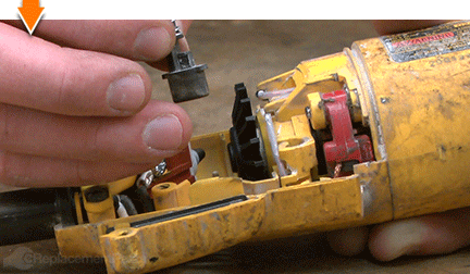
Install the lock-on button into the handle.
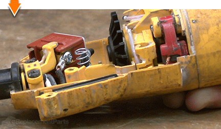
11. Reinstall the paddle assembly.
Install the paddle assembly into the handle; ensure that the tail is positioned above the switch button, and the fulcrum is seated within the recess in the handle.
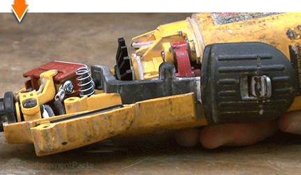
12. Reinstall the top half of the handle assembly.
Partially install the top half of the handle assembly.
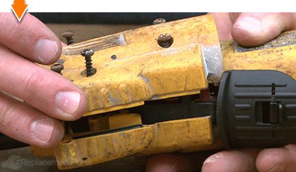
Align the posts (on the fulcrum and the lock-on button) with the recesses in the top of the handle.
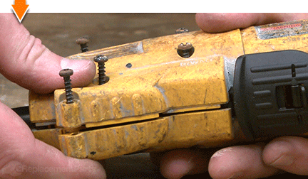
Before securing the handle with the screws, test the paddle and the lock-on button for proper functionality.
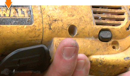
Secure the handle with the screws.
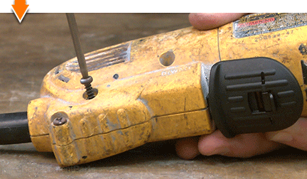

You can't place a value on a job well done, unless you did it yourself. (Which you did.) Now you can place that value back into your own pocket. (Or into your business.) Not only did you refine your grinder at a fraction of the cost of replacement; you have expanded your skills far beyond the daily grind.


