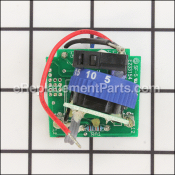
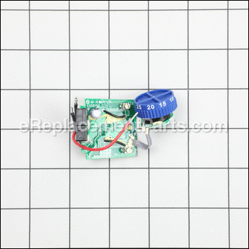
This item is a genuine Dremel replacement part that has been OEM sourced to ensure quality. The circuit board is intended to be used with rotary tools. This item fits into the motor housing and is used to relay electricity from the cord to the motor and to regulate the motor's output. This circuit board is priced as a single item.
Printed Circuit Board 2610019984
OEM part for: Dremel, Bosch
Part Number: 2610019984
Compatibility
This part will fit the following 1 machine
Dremel
This item works with the following types of products:
- Multi-Tool Parts
Customer Part Reviews ?
- 1
Questions & Answers ?
Our customer Service team is at the ready daily to answer your part and product questions.

Ask our Team
We have a dedicated staff with decades of collective experience in helping customers just like you purchase parts to repair their products.
Does this fit my product?Questions & Answers for Printed Circuit Board
Customer Repair Instructions ?
All our customer repair instructions are solicited directly from other customers just like you who have purchased and replaced this exact part.
Dremel tool stopped functioning
Tool Type
MultiTool
Difficulty
Medium
Time
30-60 minutes
Tools Used
Screwdriver, Torx T15 Screw driver.
Please read the whole process once (or more) decide if you are up for it before attempting. Get a friend to help - an extra set of eyes and hands is very helpful.
1.) UNPLUG THE TOOL. Do it NOW if you want to live.
2.) Removing the set of brushes. These are two graphite block/spring assemblies that are under two plastic caps on opposite sides of the motor.
3.) Remove the Torx T15 screws that hold the case together.
4.) Unscrew the top cap of the tool (near the collet).
5.) Remove the hanger clip (near the ac wire exiting tool). Set all the external parts in a separate bin. Keep the internal parts in a different bin. This allows you to later know that everything that belonged inside got put back (nothing left over).
6.) Carefully separate the two halves of the shell.
7.) TAKE PICTURES before going forward.
8.) Be aware that the motor assembly is now just sitting in the case - and as we go forward, it will be easily popped out so be careful to not invert things.
8.) Remove the center plastic cover piece that holds the speed control adjustment knob.
9.) Remove the two screws from the strain-relief block that clamps the AC cord. NOTE: these are also T15 screws, but they are longer. Be sure not to confuse these with the other, smaller, case screws.
10.) Loosen the flat head screws to release the AC cord wires form the PCB.
11.) Pull the PCB (printed circuit board) and knob assembly up and away - but just enough to free it. At this point you should take a marker and make some kind of mark on the motor shell
so that you can reassemble it that same way. TAKE ANOTHER PHOTO of your markings and take note of the color of the wires and the holes they are in - you will need to match this exactly when you install the new PCB.
12.) This step is where you might get a little challenged. Here you will remove the motor parts from the shell that holds them in proper alignment. The objective is to access the field coil assembly (where the wires connect). There are three wires that need to be released from their push-in self-locking clamps - much like some ac outlets. Also, it may not be obvious, but the rear most section (plastic section) of the field winding pulls off of the metal part. This is where marking it with a sharpie will ensure it is replaced correctly. SO, carefully remove the motor sections from the housing so that you can remove the part where the wires connect.
13.) To release the old wires, look for locking tabs to release the plastic cover form the case. Take care not to force anything. Once the cap is off the wires will release and the old PCB will be free. Again make sure you know what color wires go in the holes. Discard the old PCB assy.
14.) Replace the plastic cap and press the wires into the correct holes - keep in mind that you want the wires to feed nicely (straight shot - not twisted) from the new PCB through the case.
15.) Ok, seriously. You can do this. Mate the plastic part of the field coil assembly to the metal part making sure to match up the marker line(s) you made. Carefully slide the field coil assembly over the shaft (armature).
16.) Replace the motor parts into the shell. To do this you will need to make sure the black boot (about the size of a few stacked nickles) is placed over the end thrust bearing (the thing that holds the shaft end and allows it to spin).
17.) With some trial and error, you should be able to slide all the parts into their registration points in the case - refer to the many pictures you took! There is a little spring force that needs to be applied near the collet release mechanism. Also, make sure to position the threaded tube at the end of the drill so that it looks as in the photos.
18.) Check to see that the shaft spins somewhat freely.
19.) Attach the AC cord to the two flat head connector blocks and tighten until snug - do not over tighten.
20.) Now you will route the three wires into the wire channels in the shell and position the PCB into the holding slots.
21.) With the PCB in roughly the right position, replace the strain relief block using the two long torx screws. At this point things should stay in place fairly well.
22.) Double check the alignment of the motor parts, and PCB to see that it matches the photos - adjust as needed. The blue switch bar should be in position and should be able to operate the microswitch properly.
23.) Position the speed adjustment assembly and the cover into the correct position.
24.) Fit the top shell and carefully over the bottom shell, aligning the internal parts to their registration points. The two halves should mate easily and there should be no internal parts left. Before screwing it together, squeeze the shell closed firmly and verify that the motor spins freely.
25.) Replace the case screws and tighten snugly - recheck that the motor still turns freely.
26.) Screw on the collet cover end cap, just snugly.
27.) Replace the hanger
28.) Install the motor brushes and end caps - just snugly not too tight.
29.) Make sure the drill switch is in the off position and no tools are in the collet. Plug it in the out power outlet and switch on the drill. It should operate normally and check the speed control for proper operation.
30.) Turn off the drill and insert a tool to make sure that the collet clutch is correctly assembled.
Enjoy. BTW, this request for me to tell how I did it had to be done from my memory, since I had actually already fixed the drill. I tried to think of everything, but my apologies if you encounter something unexpected. Sorry I didn't video it or take pictures - I never think that anyone cares about this stiff until afterward. Good Luck!
Defective power switch on main circuit board.
Tool Type
MultiTool
Difficulty
Medium
Time
30-60 minutes
Tools Used
Screwdriver, Pliers, Torx driver, multimeter
Parts Used
2. Remove the wire bail and the case screws.
3. Separate the clamshell and remove the power cord.
4. Remove the armature and unplug the stator.
5. Remove the power cord wires from the circuit board.
6. Remove 3 circuit board wires from the brush holder.
7. Reassemble.
Would not run! Variable speed control was bad!
Tool Type
MultiTool
Difficulty
Medium
Time
30-60 minutes
Tools Used
Screwdriver
Parts Used
Faulty switch on Dremel 4200.
Tool Type
MultiTool
Difficulty
Hard
Time
15-30 minutes
Tools Used
Screwdriver, Pliers
Parts Used
OEM stands for Original Equipment Manufacturer and means the part you’re buying is sourced directly from the manufacturer who made your product. At eReplacementParts, we sell only genuine OEM parts, guaranteeing the part you’re purchasing is of better design and of higher quality than aftermarket parts.
Our product descriptions are a combination of data sourced directly from the manufacturers who made your product as well as content researched and curated by our content & customer service teams. This content is edited and reviewed internally before being made public to customers.
Our customer service team are at the ready daily to answer your part and product questions. We have a dedicated staff with decades of collective experience in helping customers just like you purchase parts to repair their products.
All our part reviews are solicited directly from other customers who have purchased this exact part. While we moderate these reviews for profanity, offensive language or personally identifiable information, these reviews are posted exactly as submitted and no alterations are made by our team.
All our customer repair instructions are solicited directly from other customers just like you who have purchased and replaced this exact part. While we moderate these reviews for profanity, offensive language or personally identifiable information, these reviews are posted exactly as submitted and no alterations are made by our team.
Based on data from past customer purchasing behaviors, these parts are most commonly purchased together along with the part you are viewing. These parts may be necessary or helpful to replace to complete your current repair.
All our installation videos are created and produced in collaboration with our in-house repair technician, Mark Sodja, who has helped millions of eReplacementParts customers over the last 13 years repair their products. Mark has years of experience in selling and repairing both commercial and residential products with a specialty in gas-powered equipment.
This data is collected from customers who submitted a repair instruction after replacing this exact part. Customers can rate how easy the repair was to complete and how long it took. We aggregate this data to provide a repair rating that allows customers to quickly determine the difficulty and time needed to perform their own repair.


