Why Read This Article?
Finish Nailer Repair - Replacing the Driver Guide (Ridgid Part # 79004001022)
Article Breakdown
Finish Nailer Repair - Replacing the Driver Guide (Ridgid Part # 79004001022)
Safety Guidelines
- Always unplug the tool before inspecting or dismantling it.
- A clean workspace can minimize the potential for accidents and prevents dismantled tools from being exposed to dirt.
- Wait for an overheated tool to completely cool down before opening it or inspecting it.
- Always wear protective eyewear and other necessary safety gear when working with power tools.
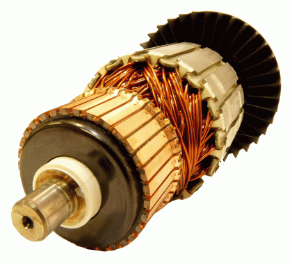 Once the cause of the malfunction or drop in tool performance is worked out, most of them can be fixed right on site. Visualizing the path that electrical energy follows through a power tool is the key to knowing why a tool only starts after being shook, why it doesn't start at all, or why sparks are flying out the dust vents.
Power-Path Logic
Since electricity follows a physical logic through a power tool, it makes sense that most malfunctions in a power tool follow the same path. Most electrical tool problems are caused by heat, shorting, or wear along the path of electrical power in the tool.
Electrical power enters the tool at one end, follows the path of wiring and connections to the tool's motor, is converted into physical energy, and leaves the tool at its working end.
Diagnosing most problems in an electric power tool means following the path that electrical power follows through the tool.
For the sake of this troubleshooting guide, we call this way of thinking about tool diagnosis "power-path logic." Power-path logic is really just simple, mechanical common sense, and it is the key idea needed to get to the root of most tool break downs.
Power-path logic goes like this:
1. Power enters a power tool at its "power end" through an outlet or battery. From there it follows a path through the different parts of the tool. The order of the major parts along the power path is:
a) the power cord,
b) the power switch,
c) the carbon brushes,
d) the commutator/armature, and
e) the field. For additional information on these tool parts, visit the article "Electric Power Tool Parts 101."
2. Power tool problems that happen closer to the power end of the tool (the end where the electrical energy enters from an outlet or battery) are more common.
This is because the parts closer to the power source are more likely to take the brunt of a power surge or heat damage. Also, parts farther down the path, like armatures and fields, are generally tougher than switches and brushes.
So, diagnosis for most problems starts at the entry end and works its way up to the exit end.
3. Many symptoms of a tool failure do not point to just one problem. Starting inspection at the entry end is always best if the source of the problem is unknown for two reasons.
a) If the source of the problem is unknown, starting at the power end is best because the problems that occur towards the power end are more common.
b) If the source of the problem is unknown, starting at the power end is best because it requires less dismantling of the tool, making the repair faster and easier.
4. Some symptoms point to specific problems in the tool, in which case power-path logic is not needed for diagnosis.
As might be expected, the steps for diagnosing most symptoms will include following the tool's power path, but every problem is different.
Before that though, an explanation about power cords and this guide is needed.
[Back to top]
Power Cords
Power cords are the point of entry of electrical energy for power tools that don't use a battery, but they are excluded from the bulk of this guide for two reasons.
1. Diagnosing a damaged or worn power cord is usually easy to do just by looking at the cord, and
2. Most problems caused by power cords in a tool can be prevented by using the correct power cord and power source. The major problem caused by power cords is that they can cause heat in the tool's motor by not supplying enough voltage. There are three major reasons why a power cord will make a tool overheat by supplying less power:
1. The cord is damaged, cut or worn. Damaged, cut, or worn cords are easy to spot and replace.3
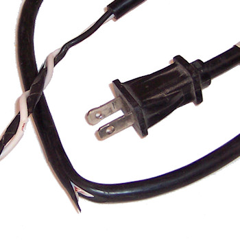
2. The wiring in the power outlet does not match the requirements of the tool.
Electric power tools should always be operated on outlets that match their specifications. A tool's amperage rating indicates how many amps a tool can handle without overheating and what kind of outlet to use for a tool. Or,
3. Because there is too much extension cord in use.
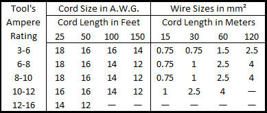
If too much extension cord is being used, the power supply can be very weak by the time the electricity gets to the tool. Luckily, charts like the one below show exactly how much extension cord should be used for each tool. Using a tool's amperage rating and the gauge of its cord with this chart will show the length limits for that tool's cord:
Recommended Extension Cord Sizes
 For more information on Power Cords--Click here.
For a "Power Cord Replacement" article--Click here.
The remainder of this troubleshooting guide assumes that:
1. Users are using the correct gauge of power cord for the power tool.
2. Users are operating power tools on outlets that match the tool's amperage rating.
3. Users are using the right length of power cord. With power cord issues ruled out from the beginning, this guide can focus on what might go wrong inside a tool past the cord. [Back to top] Troubleshooting By Symptom These are the most common red flags that a power tool needs inspection, maintenance or repair. Following each are steps to diagnose the problem and check the mostly-likely causes first. The symptoms listed in this troubleshooting guide are: Off-And-On Use A Decrease In Power Or Performance The Tool Won't Start At All Sparks And/Or Smoke Out The Dust Vents Sparks And/Or Smoke In The Switch Shaking And/Or Twisting The Tool Helps It Start Note: These symptoms are not listed in any particular order because their character and frequency can vary from tool to tool. You can click the links above to jump to the section of this article that you need. (Hint: Most of the symptoms below will follow power path logic to some degree, but some symptoms will call for starting halfway down the power path or will point to just one cause, etc. Remember, power path logic is just a general way to think about how electric power tools work and why they might malfunction.) [Back to top] Off-And-On Use There are a few things to check if a power tool works fine one minute and then doesn't even start up the next. The most likely source of this problem is the first part (after the cord) along the power path, the power switch. 1. Take a look at the switch assembly and check for damage.
- Heat damage will appear as melted or discolored wiring, or melted plastic.
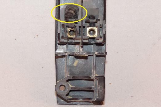
Power switches often wear out with use and just have to be replaced sometimes before they can be eliminated as the cause of off-and-on use. Shaking and twisting a tool will not help a tool start if its power switch has failed.
The best way to be sure about a power switch if there is no visible damage is to use a multitester. For a "Multitesters 101" article--Click here. For a "Power Switch Repair 101" article--Click here. If you're confident that the power switch is good and can't see any visible damage on it, then checking the brushes is next. 2. Check the brushes for heavy wear, heat damage, chips, and burrs.
- Heavy wearing will be close to or past the brush's wear lines.
- Heat damage will appear as dark areas on the brushes or discoloration of the wires/springs around the brushes.
- Chips will be clearly visible.
- Burrs will be small formations around the brush's sides or edges which can restrict a brush's movement in its holders and prevent it from contacting the commutator.
- Check that the brush springs are still "springy" and applying enough pressure.
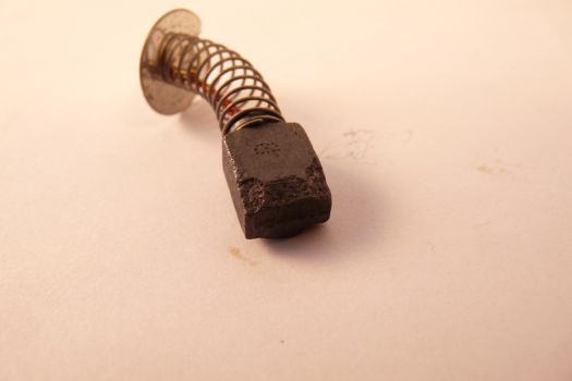
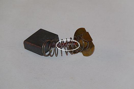
Chips, heavy wear and burrs all cause off-and-on use in a power tool because they create gaps in conductivity where the brushes meet the armature.
Burrs should be filed down, but brushes should be replaced in all other cases.
It is especially important to continue along the power path and check the armature's commutator for damage if chips are found in brushes. Chipped brushes are often cause by worn or damaged commutators, so replacing damaged brushes with new ones won't always be a lasting fix. In any case, even if no damage to the brushes is found, checking the commutator is next on the list. 3. Take a look at the commutator and check it for damage.
- Commutators should be perfectly round. High points, low points and other warping on a commutator can cause off-and-on use.
- Check for missing commutator bars. Missing pads or bars will force the electrical current to arc between gaps, causing off-and-on use.
- Look for discoloration on the commutator caused by heat damage.
- Check for buildup in the grooves between commutator bars.
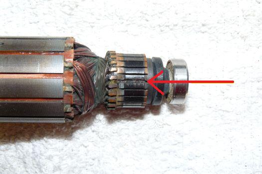
Sometimes a damaged commutator is the problem all along and it takes getting this far into the tool to discover it. This could happen if the damage to the commutator is recent and hasn't had the chance to chip or wear the brushes yet.
A damaged commutator should be replaced quickly, before it damages other components of the power tool. Also remember that these problems can appear in any combination and all show up together as a single off-and-on use issue, so checking the whole tool is often the best thing to do. [Back to top] A Decrease In Power Or Performance A decrease in power or performance in a power tool is caused by either a weak or damaged connection somewhere along the power path, by heat damage to one or more of the tool's components, or by overloading the tool. (Hint: Remember, this is assuming that power cord issues and external power source issues have already been checked out and eliminated.) Checking the power switch is the first step for many symptoms, but a failing or failed power switch will not be able to start the tool at all or only sometimes. If a tool is simply not performing with the same power as it once did and the power switch is working normally, it's probably not the power switch and starting with the brushes is the first step. 1. Check the carbon brushes for heavy wearing, chips, or signs of heat damage.
- Heavy wearing will be close to or past the brush's wear lines.
- Heat damage will appear as dark areas on the brushes or discoloration of the wires/springs around the brushes.
- Chips will be clearly visible.
- Check that the brush springs are still "springy" and applying enough pressure.


When brushes are heavily worn, chipped, or damaged like this, the tool user will often experience off-and-on use, like when power switches act up from wear or damage.
But heat damage to brushes especially can reduce the overall conductivity of the brush, causing less power to reach the motor of the tool. Bushes should be replaced in all of the above cases. If you check the brushes and they are free of wear or damage, the next step is checking the commutator. 2. Take a look at the commutator and check it for damage.
- Commutators should be perfectly round. High points, low points and other warping on a commutator can cause a decrease in tool performance.
- Check for missing commutator bars. Missing pads or bars will force the electrical current to arc between gaps, reducing overall performance.
- Look for discoloration on the commutator caused by heat damage.
- Check for buildup in the grooves between commutator bars.

Damaged commutators can cause off-and-on damage too, but they can also cause a general decrease in performance. A damaged commutator calls for replacing the armature, but it also calls for checking the rest of motor. 3. Check the rest of the armature assembly for signs of heat damage.
Heat damage will appear as melted insulation around the wires surrounding the armature assembly, or discoloration of the wires and/or insulation.
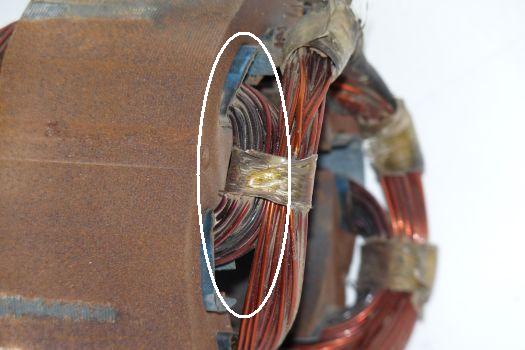
Lack of power from any source along the power path before the armature can cause the armature and motor to heat up and suffer damage. If the problem is caught before the tool sees too much low-power use, then damaging the field and other parts of the tool can be avoided.
An armature assembly that has been damaged by heat will cause a sharp decrease in tool performance. If heat damage is found on the armature, then taking a look at the field is also a good idea. Although a damaged field will cause low performance in a tool all on its own. 4. Look for heat damage on the field assembly's wires or wire insulation.
- Heat damage to a field will also appear as melted wire insulation or wire discoloration.

Fields can also fail from being overloaded if a tool is used for work that exceeds its specifications.
Most field and armature damage is obvious by other signs (like sparks or smoke coming out the dust vents) but sometimes the power decrease caused by the damage isn't noticeable before it gets too bad.
However, if you already know that the tool has been overloaded or has overheated, then you might want to plan on dismantling the tool all the way to the motor from the beginning, checking each part on the way. Also remember that these problems can appear in any combination and all show up together as a single performance decrease issue, so checking the whole tool is often the best thing to do. [Back to top] The Tool Won't Start At All If a power tool won't start at all, then the steps for diagnosing the problem are a lot like the steps for diagnosing off-and-on use. This is because the problem could be caused by damage or wear to any tool part along the power path (like with off-and-on use), but a tool not starting at all could also be caused by a damaged armature or field. 1. Take a look at the switch assembly and check for damage.
- Heat damage will appear as melted or discolored wiring, or melted plastic.

Power switches often wear out with use and just have to be replaced sometimes before they can be eliminated as the cause of a tool not starting. You can be especially sure that it is the switch though if you know that the switch has suffered water or moisture damage.
Power switch failure is the most common reason for a tool not to start at all.
The best way to be sure about a power switch if there is no visible damage is to use a multitester. For a "Multitesters 101" article--Click here. For a "Power Switch Repair 101" article--Click here. If you're confident that the power switch is good and can't see any visible damage on it, then checking the brushes is next. 2. Check the brushes for heavy wear, heat damage, chips, and burrs.
- Heavy wearing will be close to or past the brush's wear lines.
- Heat damage will appear as dark areas on the brushes or discoloration of the wires/springs around the brushes.
- Chips will be clearly visible.
- Burrs will be small formations around the brush's sides or edges which can restrict a brush's movement in its holders and prevent it from contacting the commutator.
- Check that the brush springs are still "springy" and applying enough pressure.


Sometimes the wear or damage to a carbon brush is bad enough that power isn't getting to the electric motor at all. This will keep the tool from turning on, even if the switch is fine.
This is especially true if a burr has formed on the brush. Burrs can sometimes prevent a brush from making contact with the armature at all, providing zero power to the tool motor. Any kind of heavy damage or chipping to the brushes merits taking a look at the armature as well. If there isn't any problem with the brushes, then the armature is still the next stop. So, 3. Take a look at the commutator and check it for damage.
- Commutators should be perfectly round. High points, low points and other warping on a commutator can cause a decrease in tool performance.
- Check for missing commutator bars. Missing pads or bars will force the electrical current to arc between gaps, reducing overall performance.
- Look for discoloration on the commutator caused by heat damage.
- Check for buildup in the grooves between commutator bars.

Commutator damage can be heavy enough to prevent the tool from starting at all, which means that the armature will have to be replaced, as well as any brushes damaged by the commutator.
A damaged commutator should be replaced quickly, before it damages other components of the power tool. If the brushes were fine, then it still might be heat damage to the armature that has completely disabled the tool. It would be unlikely that heat damage could fry an armature without damaging other parts of the tool, but it could still happen. 4. Check the rest of the armature assembly for signs of heat damage.
- Heat damage will appear as melted insulation around the wires surrounding the armature assembly, or discoloration of the wires and/or insulation.

A damaged armature will have to be replaced to fix the power tool and prevent further damage. It could still be the field, even if everything else up to this point has checked out fine. It's unlikely that a field could completely fail like this without obvious signs or damage to other parts of the tool, but it can still happen. 5. Look for heat damage on the field assembly's wires and wire insulation.
- Heat damage to a field will also appear as melted wire insulation or wire discoloration.

Fields fail most often from being overloaded if a tool is used for work that exceeds its specifications. Damaged fields should be replaced quickly. Also remember that these problems can appear in any combination and can all show up together as a single electrical connection issue, so checking the whole tool is often the best thing to do. [Back to top] Sparks And/Or Smoke Out The Dust Vents This is one where power-path logic isn't needed. If sparks or smoke are coming out of a tool's dust vents, either the tool's armature or fieldor both. is damaged and failing, In fact, most armature and field problems described in the above symptoms will have obvious signs like sparking and smoke. Both the armature and field should be checked for wear and heat damage. 1. Take a look at the commutator and check it for damage.
- Commutators should be perfectly round. High points, low points and other warping on a commutator can cause a decrease in tool performance.
- Check for missing commutator bars. Missing pads or bars will force the electrical current to arc between gaps, reducing overall performance.
- Look for discoloration on the commutator caused by heat damage.
- Check for buildup in the grooves between commutator bars.

A damaged commutator can make the carbon brushes bounce and spark as the armature spins. Severe sparks and smoke is usually because of more severe heat damage to the rest of the armature though. 2. Check the rest of the armature assembly for signs of heat damage.
- Heat damage will appear as melted insulation around the wires surrounding the armature assembly, or discoloration of the wires and/or insulation.

A damaged armature will have to be replaced to fix the power tool and prevent further damage. Even if the armature checks out fine, it could still be the field. It's unlikely that a field could completely fail like this without obvious signs or damage to other parts of the tool, but it can still happen. 3. Look for heat damage on the field assembly's wires or wire insulation.
- Heat damage to a field will also appear as melted wire insulation or wire discoloration.

Fields fail most often from being overloaded if a tool is used for work that exceeds its specifications. Damaged fields should be replaced quickly. [Back to top] Sparks And/Or Smoke In The Switch This one goes without saying, the power switch just shorted out. Replacing the switch will be the first step toward getting the tool operational and checking the tool for signs of being damaged by the shortage in other areas. This kind of shortage in a switch will happen most often because of moisture or water getting into the switch assembly.
- The best way to be sure about a power switch if there is no visible damage is to use a multitester.
- Heavy wearing will be close to or past the brush's wear lines.
- Heat damage will appear as dark areas on the brushes or discoloration of the wires/springs around the brushes.
- Chips will be clearly visible.
- Burrs will be small formations around the brush's sides or edges which can restrict a brush's movement in its holders and prevent it from contacting the commutator.
- Check that the brush springs are still "springy" and applying enough pressure.


It's possible for all of the above brush issues to cause a tool not to start until shaken, but the most likely are chips, burrs and worn-out springs.
Burrs should be filed down, but brushes should be replaced in all other cases. As wear or damage to the carbon brushes increases, shaking and twisting the tool won't help to start the tool eventually.
It is especially important to continue along the power path and check the armature's commutator for damage if chips are found in brushes. Chipped brushes are often cause by worn or damaged commutators, so replacing damaged brushes with new ones won't always be a lasting fix. In any case, even if no damage to the brushes is found, checking the commutator is next on the list. 2. Take a look at the commutator and check it for damage.
- Commutators should be perfectly round. High points, low points and other warping on a commutator can cause a decrease in tool performance.
- Check for missing commutator bars. Missing pads or bars will force the electrical current to arc between gaps, reducing overall performance.
- Look for discoloration on the commutator caused by heat damage.
- Check for buildup in the grooves between commutator bars.

When it comes to commutator damage, shaking or twisting the tool will eventually do nothing to help the tool start up as the damage worsens.
A damaged armature will have to be replaced to fix the power tool and prevent further damage.
[Back to top]
Conclusion
Understanding how electric power tools work is the first step towards diagnosing the problems they have over time. In general, following the power path through a tool is the best way to narrow down the possibilities.
The great news is that if you can figure out the problem, you've usually cleared the highest hurdle. Finding and ordering the right parts for power tools is fast and easy, and speedy shipping options are usually available.
From there, repair guides and a little well-spent time on the part of the tool user can seal the deal and get the tool working like new again.
From our Home Page, customers can navigate through our website to several resources related to power tool diagnosis. Our tool repair forum and discussion boards address diagnosis and repair issues. Customers can also begin parts searches with a tool or machine's model number, or by selecting the tool brand or category.
[Back to top]
What we're about.


