Why Read This Article?
Finish Nailer Repair - Replacing the Driver Guide (Ridgid Part # 79004001022)
Article Breakdown
Finish Nailer Repair - Replacing the Driver Guide (Ridgid Part # 79004001022)
Tools & Materials
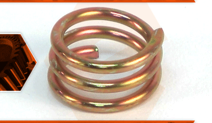

Chainsaw need a checkup? It's time to face the fix. Whether you are a legendary lumberjack or a weekend woodworker, eReplacementParts.com provides the parts, procedures and facts you need to fearlessly fix what fails you.
Is there no oil coming from your saw's oiler? You might want to inspect the spring worm gear. The spring worm gear slides onto the engine's crankshaft. The worm gear engages with a gear in the oil pump, causing the pump to send oil to the bar and chain.
The spring worm gear can slip on the crankshaft and can wear down over time (until it no longer rotates).
This article provides step-by-step instructions for removing and installing the spring worm gear on a Poulan chainsaw.
Let's get started.
 REMOVING THE SPRING WORM GEAR [top]
1. Remove the clutch cover assembly.
Remove the (2) nuts from the bar mounting bolts.
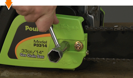
Rotate the chain tensioner screw counterclockwise to release tension from the chain.
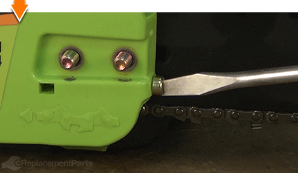
Remove the clutch cover assembly.
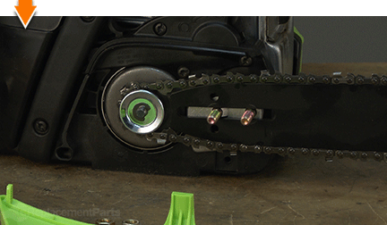
2. Remove the bar and chain assembly.
Remove the bar and chain assembly from the saw.
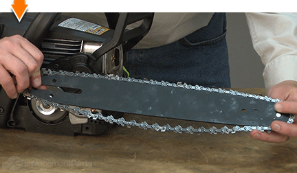
3. Remove the clutch drum.
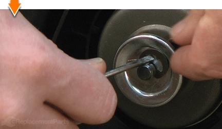
Use a small screwdriver to pry the clutch drum retaining clip away from the shaft.
Remove the clutch drum washer from the clutch drum.
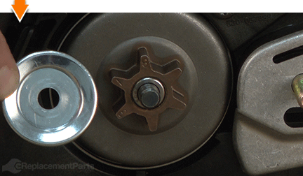
Slide the clutch drum away from the clutch assembly.
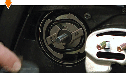
Remove the inner (small) clutch drum washer.
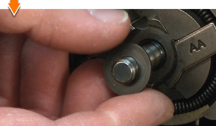
4. Remove the clutch assembly.
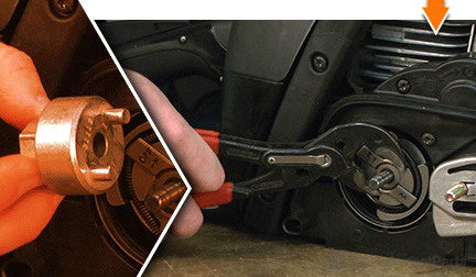
There are several methods for loosening the clutch assembly. The simplest method (and the method described in this article) is to use a clutch removal tool and an impact driver. If you do not have a clutch removal tool (or an impact driver), you can still loosen the clutch assembly using a pair of adjustable pliers. However, you will need to bind the engine with a piece of old starter rope before attempting to rotate the clutch assembly.
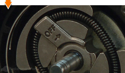
The clutch is often (but not always) reverse-threaded. There should be a stamp indicating which direction to rotate the clutch assembly for removal (or installation). This particular clutch assembly is marked with an arrow and the letters "OFF."
Place the clutch removal tool onto the clutch assembly.
Use an impact driver (and socket) to loosen the clutch assembly.
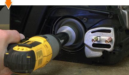
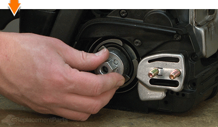
Continue rotating the clutch (by hand) as necessary.
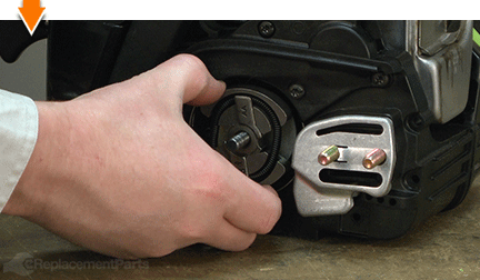
Remove the clutch assembly from the spindle.
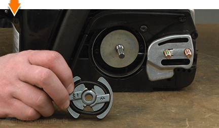
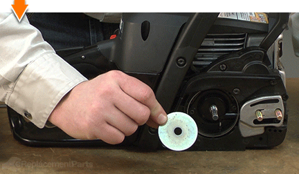
Remove the large clutch washer from the spindle.
5. Remove the front handle.
Remove the (2) screws securing the front handle to the side of the saw.
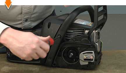
Remove the (2) screws securing the front handle to the bottom of the saw.
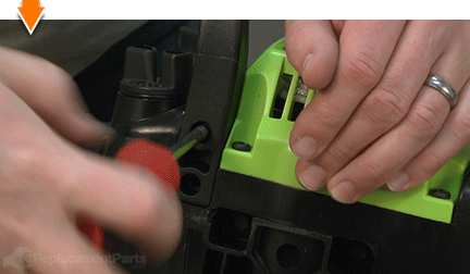
Remove the front handle assembly from the saw.
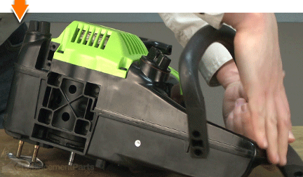
6. Remove the chain brake assembly.
Press the hand guard forward to engage the chain brake.
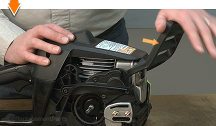
Remove the (4) screws securing the chain brake assembly to the saw.
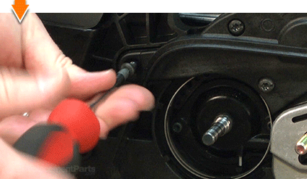
Remove the chain brake assembly away from the saw.
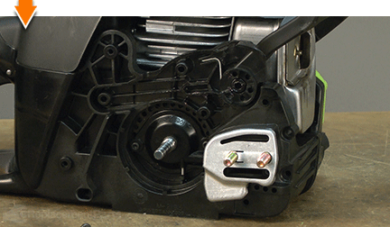
7. Remove the oil pump assembly.
Remove the (2) screws securing the oil pump assembly to the saw.
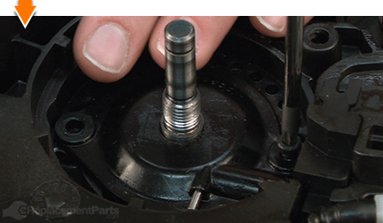
Use a small screwdriver to pry the oil feed tube from the oil pick-up assembly on the oil tank.
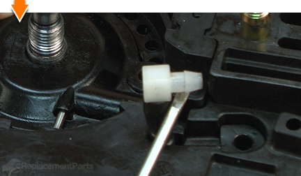
Use a small screwdriver to pry the oil pump assembly out of the housing.
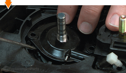
Remove the oil pump from the saw.
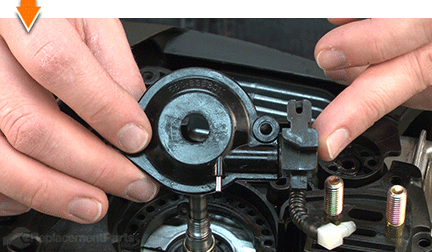
8. Remove the spring worm gear.
Use a screwdriver to gently pry the spring worm gear away from the groove on the crankshaft.
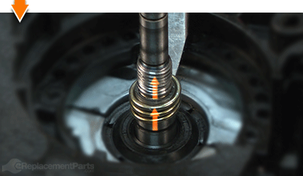
Remove the spring worm gear.
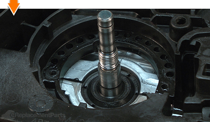
INSTALLING THE NEW SPRING WORM GEAR [top] 9. Install the spring worm gear.
Slide the new spring worm gear onto the crankshaft.
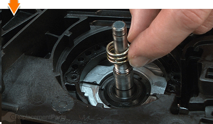
Locate a socket that is deep enough to surround the crankshaft; and small enough (in diameter) that it sits on top of the spring.
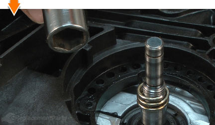
Position the socket over the crankshaft (on top of the spring).
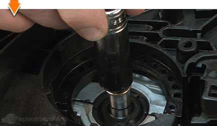
Tap the socket with a rubber mallet to seat the new spring on the crankshaft.
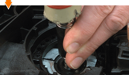
Use a screwdriver (as needed) to align the bottom of the spring with the groove on the crankshaft.
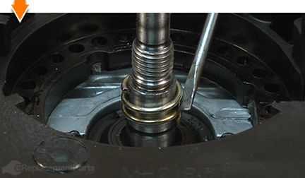
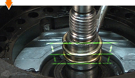
Use a screwdriver (as needed) to adjust the spring until the gaps are approximately even.
REASSEMBLING THE UNIT [top] 10. Reinstall the oil pump assembly.
Install the oil pump assembly onto the spindle.
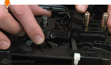
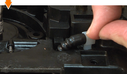
Install the oil feed tube into the oil pick-up assembly on the oil tank.
Secure the oil pump assembly with the (2) screws.
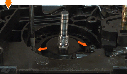
11. Reinstall the chain brake assembly.
Install the chain brake assembly onto the saw.
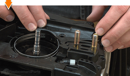
Slide the hand guard (backward or forward) as-needed to align the two components.
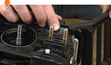
Secure the chain brake assembly with the (4) screws.
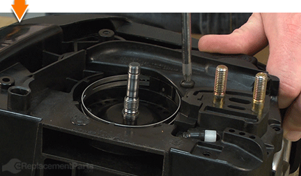
12. Reinstall the front handle.
Install the front handle onto the saw.
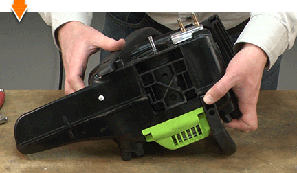
Secure the front handle with the (2) bottom screws.
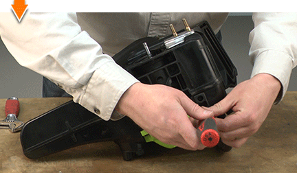
Secure the front handle with the (2) side screws.
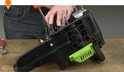
13. Reinstall the clutch assembly.
Install the large clutch washer onto the spindle.
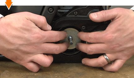
Thread the clutch assembly onto the spindle (in a counterclockwise direction) until it is hand-tight.
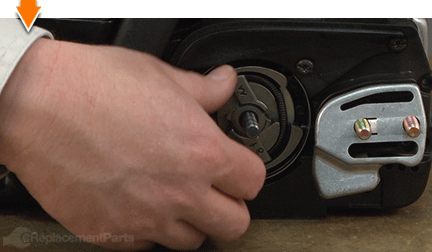
Place the clutch removal tool onto the clutch assembly.
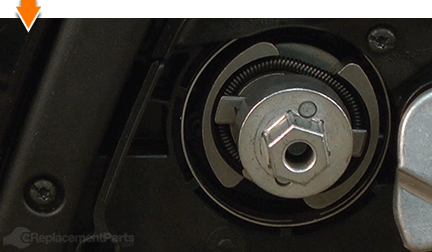
Use an impact driver (and socket) to tighten and secure the clutch assembly.
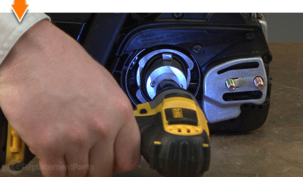
14. Reinstall the clutch drum.
Install the inner (small) clutch drum washer.
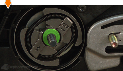
Install the clutch drum onto the clutch.
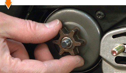
Install the outer (large) clutch washer.
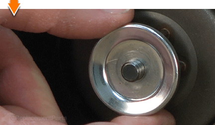
Align the clutch retaining clip with the shaft.
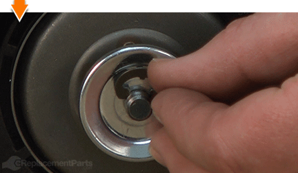
Use long-nosed pliers to seat the retaining clip on the shaft (and secure the clutch drum).
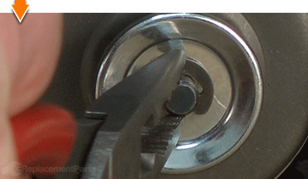
15. Reinstall the bar and chain.
Lay the bar on a flat surface.
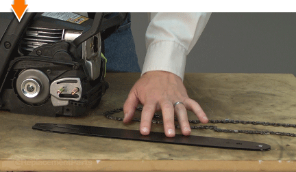
Install the chain onto the bar; ensuring that the sharp side of the teeth (along the bottom of the bar) are facing the saw.
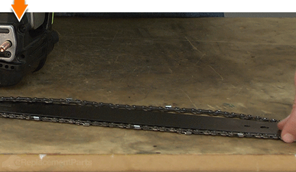
Partially install the bar and chain assembly onto the saw, ensuring that the chain engages the drive sprocket on the clutch drum.
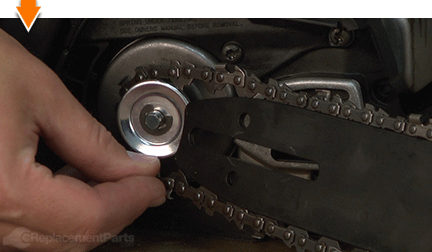
Continue installing the bar (and chain) over the bar bolts.
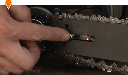
Pull the bar assembly forward (away from the engine) to align the drive links (on the chain) with the groove in the bar.
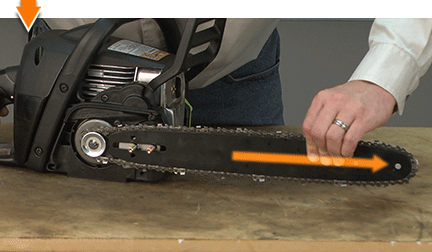
16. Reinstall the clutch cover assembly.
Install the clutch cover assembly.
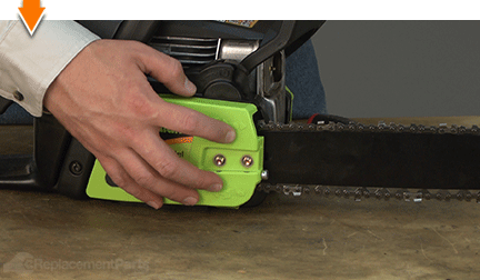
Apply (side) pressure to the clutch cover assembly.
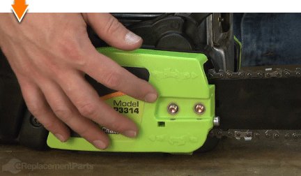
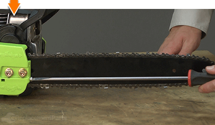
Using a long screwdriver, rotate the tensioner screw (in either direction) until the bar adjustment pin engages the hole on the bar. (The entire assembly should snap into place when this occurs).
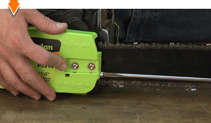
Once the adjustment pin engages the bar; rotate the tensioner screw in the opposite direction until the chain begins to tension.
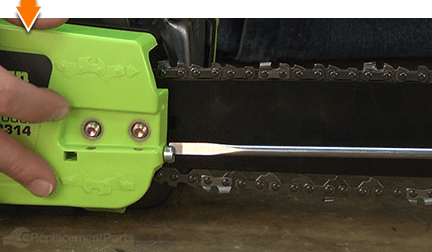
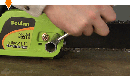
Install and hand-tighten the bar nuts.
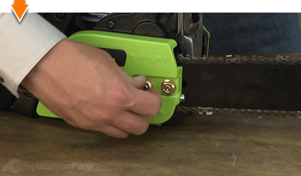
17. Tension the chain.
Grasp and raise the distant end of the bar and chain assembly (opposite the engine) until the saw begins to rise.
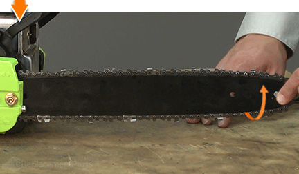
While holding the bar in the raised position, grasp the chain at the center (and top) of the bar.
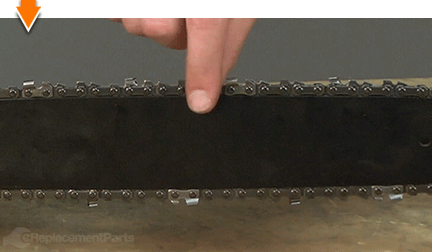
Lift the chain away from the bar assembly and inspect the gap between the two components.
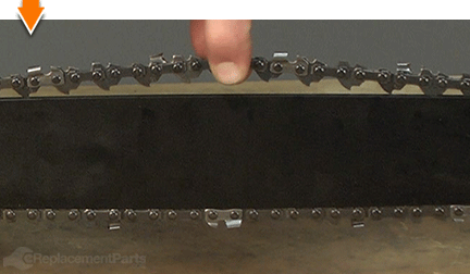
The chain is tensioned correctly when the weight of the chain does not cause it to sag below the guide bar.
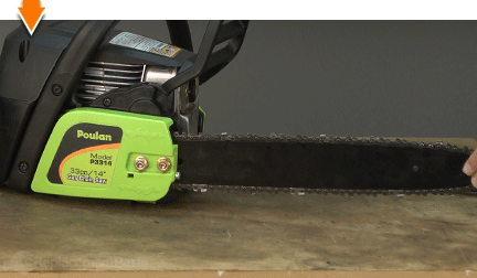
Rotate the tensioner screw (as necessary) to tighten or loosen the chain until it is correctly tensioned.
Tighten the bar nuts to secure the clutch cover assembly.

Do-it-yourself repairs like these are easier than you might think: From lawn machines to cordless drills, kitchen mixers to outdoor grills. Our "how-to" articles walk you through each repair from start to finish.
So, doing-it-yourself means never having to do it alone.


