Why Read This Article?
Finish Nailer Repair - Replacing the Driver Guide (Ridgid Part # 79004001022)
Article Breakdown
Finish Nailer Repair - Replacing the Driver Guide (Ridgid Part # 79004001022)
Tools & Materials
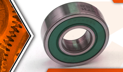

Router ball bearing been bawling? It's time to face the fix. Whether you are a master carpenter or a weekend woodworker, eReplacementParts.com provides the parts, procedures and facts you need to fearlessly fix what fails you.
The lower armature bearing on your router takes a lot of abuse. Not only does it have to withstand 20,000+ rpm, but it also endures significant side loads when the router is pushed against the work piece. Symptoms of a worn out lower bearing will be unusual sounds (ticking, squealing, screeching) or excessive heat on the motor housing (near the bearing).
Rotating the spindle manually (by hand) is another way to test the bearing. If the spindle offers any resistance (does not rotate freely), the lower armature bearing should be replaced.
This article provides step-by-step instructions for removing and installing the lower (large) ball bearing on a Porter Cable 690 series router.
Let's get started.
 REMOVING THE LOWER BEARING [top]
1. Separate the motor from the base.
Open the clamp (using the clamp knob).
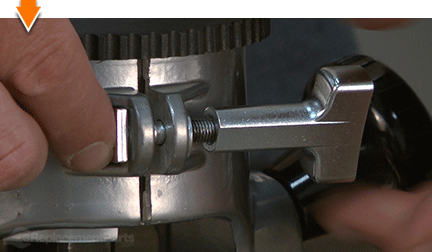
While holding the power unit, rotate the base CLOCKWISE until the lower pin in the motor housing is disengaged from the groove in the base.
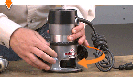
Lift the power unit free from the base assembly.
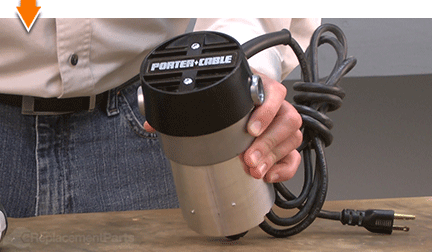
2. Remove the motor housing cap.
Remove the (2) screws from the motor housing cap.
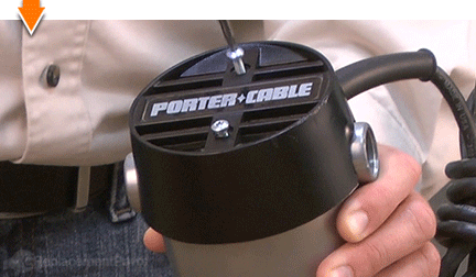
Remove the motor housing cap from the motor unit.
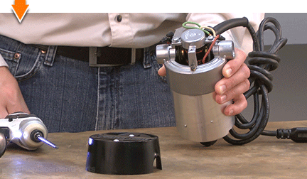
3. Remove the motor brushes.
Use a large screwdriver to loosen the brush cap.
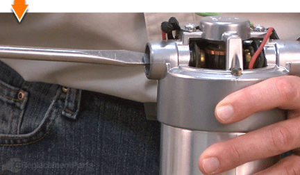
Remove the brush cap.
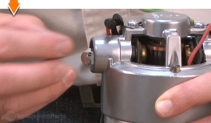
Remove the motor brush.
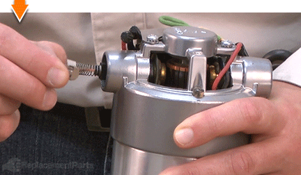
Repeat this step to remove the second motor brush.
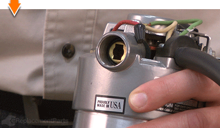
4. Separate the power unit from the case.
Use a marker to draw a line across the intersection of the power unit and the front case. This line will be used in later steps to help realign and reassemble the unit.
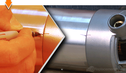
Remove the (2) retaining screws from the power unit.
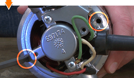
Use a rubber mallet to tap the power unit until it breaks free from the case.
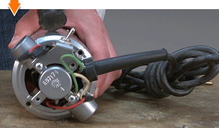
Separate the power unit from the front case.
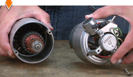
5. Remove the chuck from the armature spindle.
Remove the collet from the chuck.
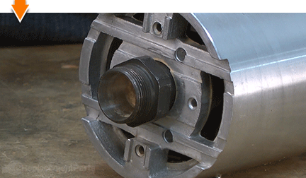
Firmly grasp the exposed portion of the armature (use a shop towel or a leather glove to help protect your hand).
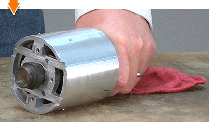
Use an impact driver and socket (or a 1 1/8-inch wrench) to loosen the chuck.
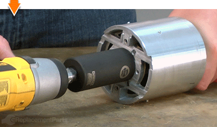
Remove the chuck from the armature spindle.
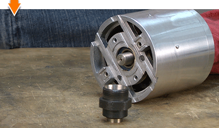
6. Remove the armature from the case.
Note: The armature is secured to the case via the lower bearing. This task is best accomplished using a bearing press. However, many people do not have immediate access to a press. As such, these steps describe an alternative method for removing the armature from the bearing (and case).
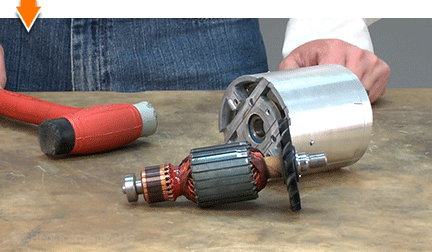
Firmly grasp the case with one hand.
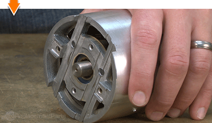
Use a rubber mallet to repeatedly strike the end of the shaft until the armature is disengaged from the bearing.
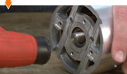
Remove the armature assembly from the case.
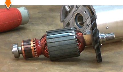
7. Remove the lower (large) bearing from the case.
Use snap-ring pliers to remove the snap-ring from the bearing (inside the case).
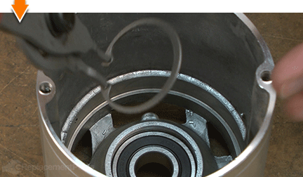
Position the open end of the case flatly upon the work surface; the bearing should be at the top.
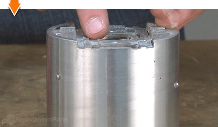
Locate a socket that is approximately the same diameter as the the inner race of the bearing.
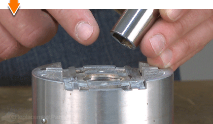
Position the socket squarely upon the inner race of the bearing.
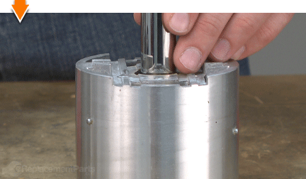
Use a rubber mallet to tap the socket until the bearing breaks free from the case.
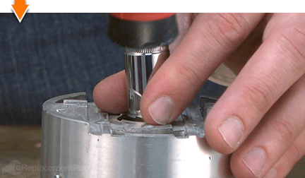
Remove the bearing from the case.
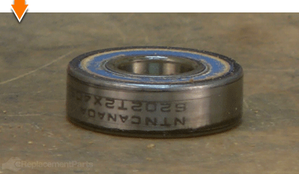
INSTALLING THE NEW LOWER BEARING [top] 8. Install the new lower (large) bearing.
Insert the new bearing into the case assembly.
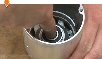
Locate a socket that is approximately the same diameter as the OUTER race of the bearing.
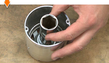
Position the socket squarely upon the outer race of the bearing.
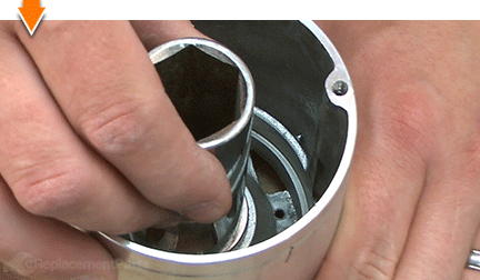
Use a rubber mallet to tap the socket and seat the new bearing in the housing.
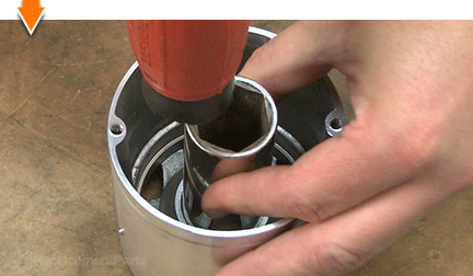
Use snap-ring pliers to reinstall the snap-ring.
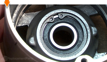
REASSEMBLING THE UNIT [top] 9. Reinstall the armature into the case.
Install the armature into the case.
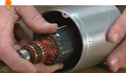
Use a rubber mallet to tap the end of the armature and press the shaft into the lower bearing.
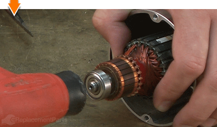
10. Reinstall the chuck.
Thread the chuck onto the spindle.
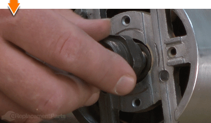
Firmly grasp the exposed portion of the armature (use a shop towel or a leather glove to help protect your hand).
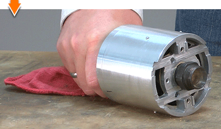
Use an impact driver and socket (or a 1 1/8-inch wrench) to secure the chuck.
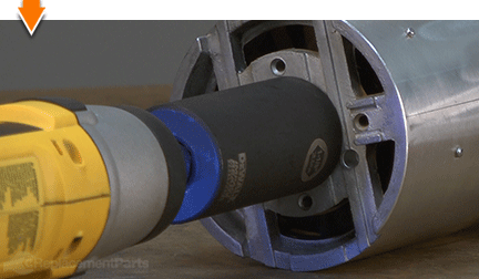
11. Reconnect the power unit to the case.
Slide the armature (in the motor case) through the field (in the power unit).
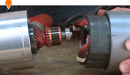
Rotate the components as necessary to align the reference marks (made earlier) on the case and the power unit.
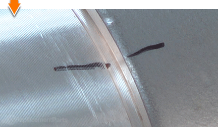
Secure the power unit to the case with the (2) screws.
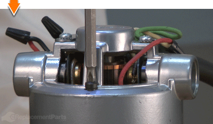
12. Reinstall the motor housing cap.
Inspect the wiring around the power unit for potential pinch points. Adjust the wires as necessary.
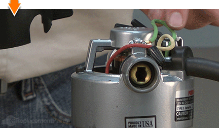
Install the motor housing cap onto the power unit.
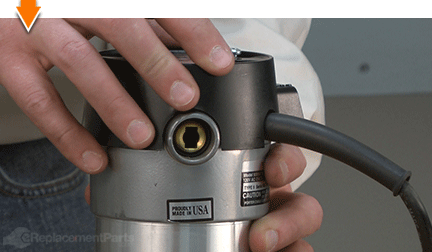
Secure the motor housing cap with the (2) screws.
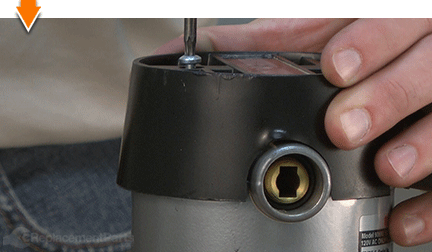
13. Reinstall the motor brushes and caps.
Slide the motor brush into the brush holder.
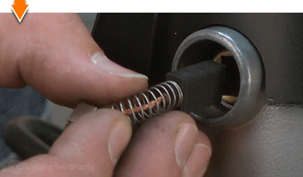
Align the tabs on the motor brush with the slots on the brush holder and compress the brush (spring) into the holder.
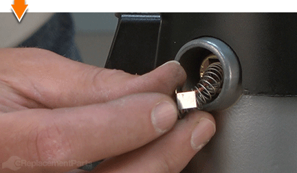
Continue holding the compressed motor brush in place with one finger.
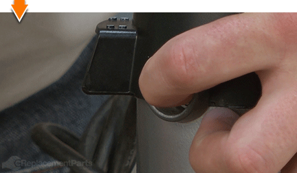
Carefully slide the brush cap into position over the compressed motor brush (as you remove your finger from the end of the brush). You may have to attempt this step a few times to get it right. The goal is to install the brush cap without allowing the tabs of the compressed motor brush to spring out of the slots in the brush holder.
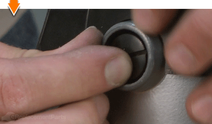
Use a large screwdriver to secure the brush cap (do not over-tighten).
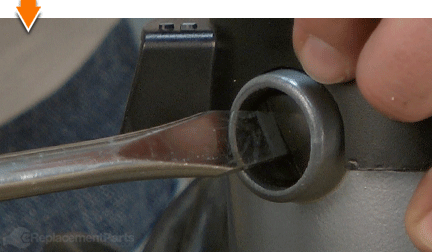
Repeat this step to install the remaining motor brush and cap.
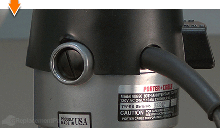
14. Reconnect the motor unit to the base.
Set the motor unit into the base.
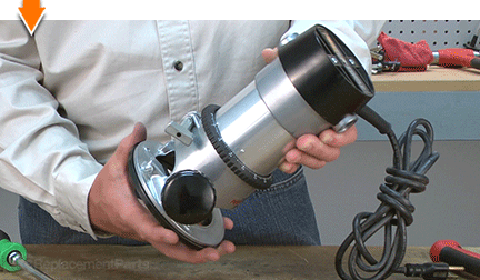
Rotate the base COUNTERCLOCKWISE until the upper guide pins motor are set in the groove of the base.
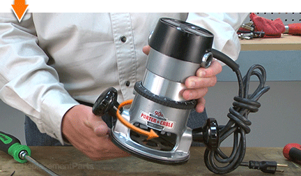
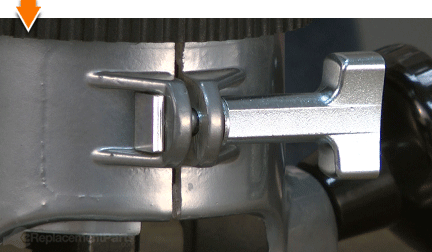
Tighten the clamp to secure the unit.

Dovetails. Rabbets. Dados. Grooves: The possibilities are as priceless as machines that create them. But you don't have to be a carpenter to cut out the middle-man. Repairing your own powered equipment is easy and economical when you follow our step-by-step guides. Not only did you restore your router at a fraction of the cost of replacement; you built on your ability to face the next fix, whatever it may be.


