
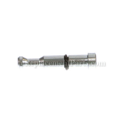

Stopper Pin Assy 302518
Part Number: 302518
")
Order within the next 8 hours
and your part ships today!
and your part ships today!
Product Information
Description:
| This is an OEM Hitachi part directly sourced from the manufacturer for use in compound miter saws. The stopper pin assembly goes next to the o-ring and fits into the hinge. During the installation process, a set of pliers might be needed to replace this part. It will require replacing if it becomes broken or bent. This is made of metal and is available as an individual replacement part. |
Frequently Purchased With

Compatibility
the 39 compatible machines
This part is compatible with the following machines:
Metabo HPT (Hitachi)
C10FCE2 10" Compound Miter Saw
C10FCE2 10" Compound Miter Saw
C10FCH2 10" Laser Compound Miter Saw
C10FCH2 10" Laser Compound Miter Saw
C12FCH 12" Laser Compound Miter Saw
C12FCH 12" Laser Compound Miter Saw
C12FDH 12" Laser Dual Compound Miter Saw
C12FDH 12" Laser Dual Compound Miter Saw
C12LCH 12" Compound Miter Saw
C12LCH 12" Compound Miter Saw
C12LDH 12" Dual Compound Miter Saw
C12LDH 12" Dual Compound Miter Saw
C12LC 12" LCD Compound Miter Saw
C12LC 12" LCD Compound Miter Saw
C10FCH 10" Laser Compound Miter Saw
C10FCH 10" Laser Compound Miter Saw
C10FCE 10" Compound Miter Saw
C10FCE 10" Compound Miter Saw
C10FCB 10" Compound Miter Saw
C10FCB 10" Compound Miter Saw
C8FSE Slide Compound Saw
C8FSHE Slide Compound Saw
C10FSH Slide Compound Saw
C10FSB Slide Compound Saw
C10FCGSM 10 Inch Single Bevel Miter Saw 15 Amp 5000 Rpm Motor W Carrying Handle
C10FCH2SM 10 Inch Compound Miter Saw With Laser Marker
C10FSBSM 10-Inch Sliding, Dual Compound Miter Saw 12 Amp 3800 Rpm 5/8 Inch Arbor W/O Laser
C10FSHSM 10-Inch Sliding, Dual Compound Miter Saw With Laser Marker W/Laser 12 Amp 3800 Rpm 5/8 Incharbor
C8FSESM 8-1/2-Inch Sliding Compound Miter Saw
C8FSHESM 8-1/2-Inch Sliding Compound Miter Saw With Laser And Light
C10FCHE2
C10FSBE2
C10FSBP4
C10FSHE2
C10FSHPS
C12FCHE2 Hammer Drill
C12LCE2 Hammer Drill
C12LCHE2 Hammer Drill
C8FC
Products Compatibility
This item works with the following types of products:
- • Miter Saw
- • Saw
Questions & Answers for Stopper Pin Assy
No questions have been asked yet
Repair Instructions: Submitted by Customers Like You
Tool Type:
Miter Saw
Parts Used:
Repair Difficulty:
Easy
Time Spent Repairing:
Less than 15 minutes
Tools Used:
Wrench Set
Vibration from hauling my miter saw back and for to work had caused the stopper pin to break
It was much easier than I had anticipated. I thought that I would have to remove the pivot pin in order to access the stopper pin. Not the case
1) On the left side of the saw (from the front) remove the up limit bolt
2) Allow the return spring to raise the saw, be careful not to let it go to far or it can effect the operation of the laser pointer (I found this out the hard way)
3) Use a screw driver or a punch to remove the broken stopper pin, be sure the old O ring comes out also
4) Put a little tool oil or WD40 on the O ring on the new stopper pin
5) Slide the new stopper pin into location
6) Pull down the saw and replace the up limit bolt and tighten
You're done
Did you find this story helpful?
Thanks for voting and helping fellow customers!
Tool Type:
Miter Saw
Parts Used:
Repair Difficulty:
Medium
Time Spent Repairing:
30-60 minutes
Tools Used:
Screwdriver, Allen Keys (Hex)
Stop Pin (aka lock pin) bent making it impossible to lock saw in closed position
Using a Philips head screw driver remove the two screws holding the Dust Guide Assembly (40) in place.
Extend the rear support (holder part # 137) to avoid tipping
Remove special screw (#290) from the Link (#288) freeing the saw blade assembly.
Remove Hex Socket HD. Bolt (243) from the gear case (244). This is located toward the rear of the link. When engaged it rests on the Hinge (34) preventing the saw from over travel.
With the Link and Hex Socket HD. Bolt now removed the saw blade assembly will now travel beyond what is normal in the raised position.
Now remove the two bolts holding the laser assembly (10) in place and move it just slightly to the left.
You can now remove the Stop Pin (Lock Pin) pulling it in toward the laser assembly.
Reverse steps to reassemble.
Did you find this story helpful?
Thanks for voting and helping fellow customers!
Reviews
1 Reviews
Average Rating (out of 5):
Click to filter by ratings:
5 stars
0
4 stars
0
3 stars
1
2 stars
0
1 stars
0
< PREV
- 1
Great part. Matches OE part perfectly.
Part is not installed yet. Will complete review after installed.
Guest -
March 24, 2023
Verified Purchase
Verified Purchase
eReplacementParts Team
< PREV
- 1
Product Information