Why Read This Article?
Finish Nailer Repair - Replacing the Driver Guide (Ridgid Part # 79004001022)
Article Breakdown
Finish Nailer Repair - Replacing the Driver Guide (Ridgid Part # 79004001022)
Tools & Materials
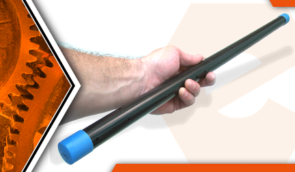

Drive shaft damaged? It's time to face the fix. Whether you are a legendary landscaper or a weekend weed whacker, eReplacementParts.com provides the parts, procedures and facts you need to fearlessly fix what fails you.
The upper drive shaft (and housing) attaches to the engine on your trimmer. The opposite end attaches to the various accessories. The most common reason for replacing the upper drive shaft is damage (usually wear) to the coupling where the accessories attach. Replacing the shaft is easy to do.
This article will show you how to remove and install the upper drive shaft and housing on a Ryobi trimmer.
Let's get started.
 REMOVING THE UPPER DRIVE SHAFT [top]
1. Disconnect the accessory.
Loosen the adjustment knob.
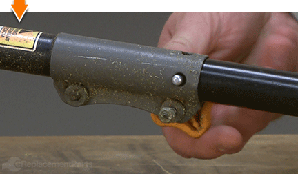
Depress the locking tabs on the accessory.
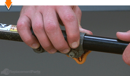
Slide the accessory out of the upper housing.
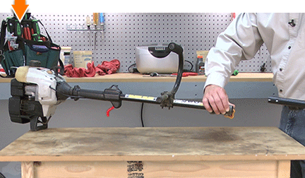
2. Remove the throttle assembly.
Remove the (5) retaining screws from the throttle housing.
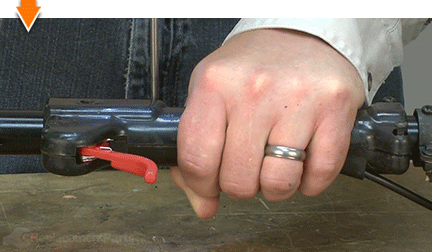
Remove the (1) anti-rotation screw from the throttle housing.
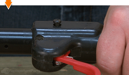
Separate the two halves of the throttle housing.
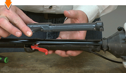
Remove the lower half of the throttle housing from the shaft.
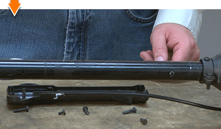
3. Remove the upper shaft from the engine.
Remove the anti-rotation screw from the upper clamp assembly.
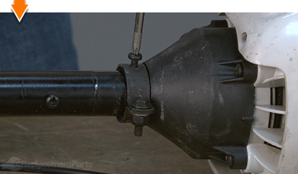
Loosen the bolt/nut on the band clamp assembly.
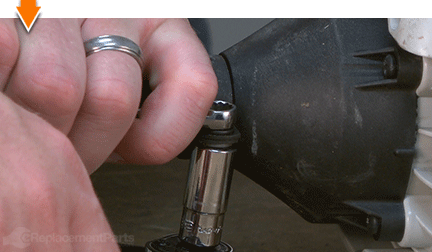
Slide the band clamp assembly away from the clutch housing.
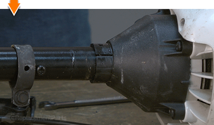
Disconnect the upper drive shaft from the engine.
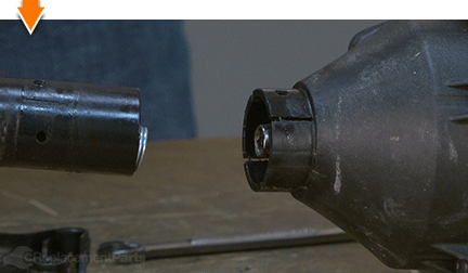
DISASSEMBLING THE OLD SHAFT [top] 4. Remove the engine-side components from the old shaft.
Remove the spring from the end of the drive shaft.
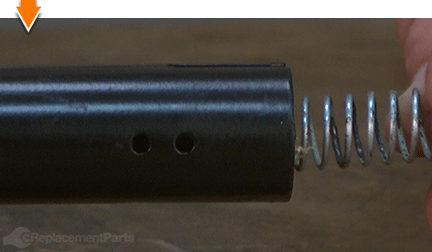
Remove the anti-rotation screw from the shaft.
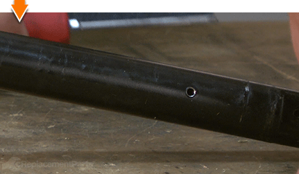
Remove the band clamp assembly from the shaft.
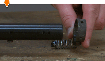
5. Remove the handle.
Remove the anti-rotation screw from the lower handle clamp.
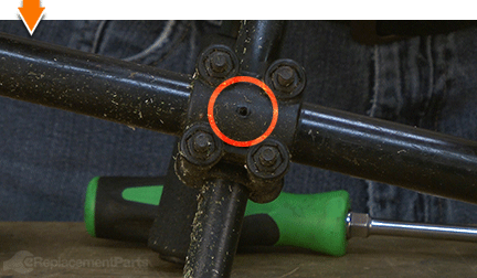
Loosen the (4) screws on the upper handle clamp.
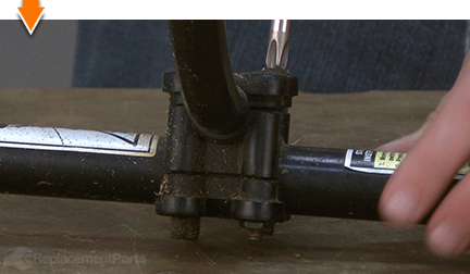
Slide the handle and clamp assembly off of the old drive shaft.
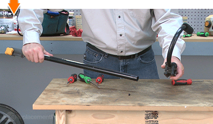
6. Remove the accessory clamp.
Remove the anti-rotation screw from the accessory clamp.
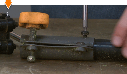
Loosen the screw securing the accessory clamp to the shaft.
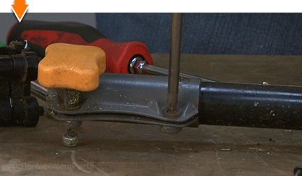
Remove the accessory clamp from the old shaft.
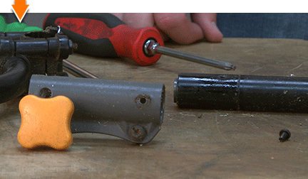
INSTALLING THE NEW DRIVE SHAFT [top] 7. Install the accessory clamp onto the new shaft.
Note that one end of the shaft contains a squared coupler (which connects to the trimmer attachments). The reverse end of the shaft housing contains a milled slit (through which the drive cable can be seen). The milled end attaches to the trimmer engine.
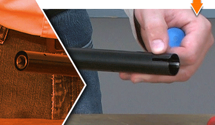
Slide the accessory clamp onto the new shaft until the holes (for the anti-rotation screw) align.
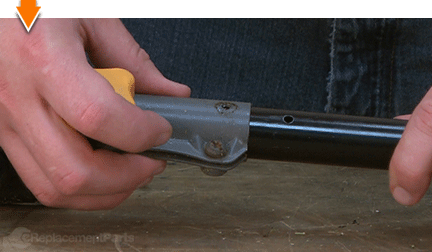
Install the anti-rotation screw onto the accessory clamp.
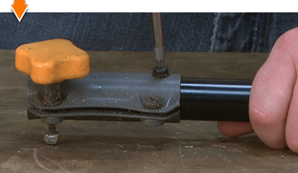
Tighten the accessory clamp screw.
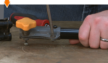
8. Install the handle.
Slide the handle onto the new upper shaft until the holes (for the anti-rotation screw) align. Use the hole that is closest to the accessory clamp.
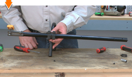
Install the anti-rotation screw onto the lower handle clamp.
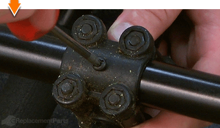
Tighten the (4) screws on the upper handle clamp to secure the handle.
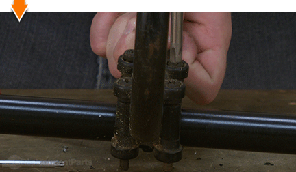
9. Install the engine-side components onto the new shaft.
Install the anti-rotation screw (this screw prevents the inner cable liner from rotating).
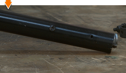
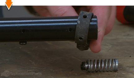
Slide the band clamp accessory onto the new shaft.
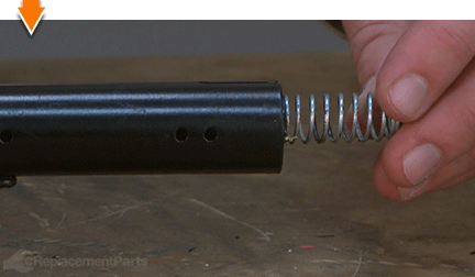
Install the spring into the end of the upper shaft housing (the wider end of the spring should face the engine).
10. Install the upper drive shaft onto the engine.
Slide the new drive shaft into the clutch housing. The milled slit on the drive shaft should face the fuel tank. The spring should fit around the clutch drum.
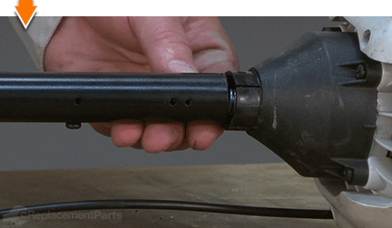
Rotate the drive shaft until the holes for the anti-rotation screw align.
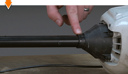
Slide the band clamp onto the clutch housing and rotate the clamp until the holes for the anti-rotation screw align.
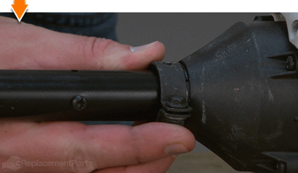
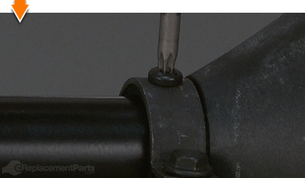
Install the anti-rotation screw onto the band clamp assembly.
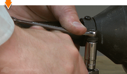
Tighten the bolt/nut to secure the band clamp assembly.
REASSEMBLING THE UNIT [top] 11. Reinstall the throttle assembly.
Install the bottom half of the throttle housing onto the upper shaft.
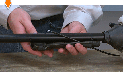
Verify that the throttle trigger, spring and cable are neatly aligned within the housing.
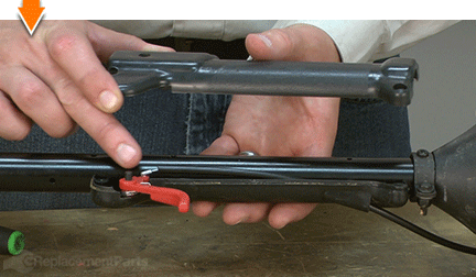
Install the top half of the throttle housing.
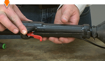
Secure the top half of the throttle housing with the (5) screws.
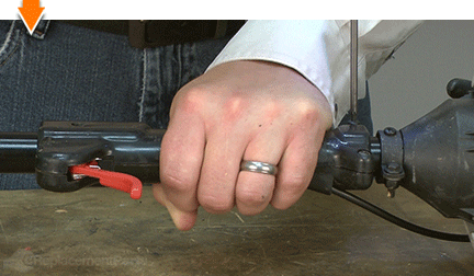
12. Reinstall the anti-rotation screw.
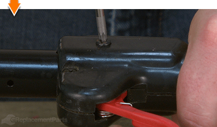
Install the anti-rotation screw. Note that there are two different mounting holes on the metal drive shaft housing. The anti-rotation screw should be installed into the hole that is closest to the trimmer's engine.
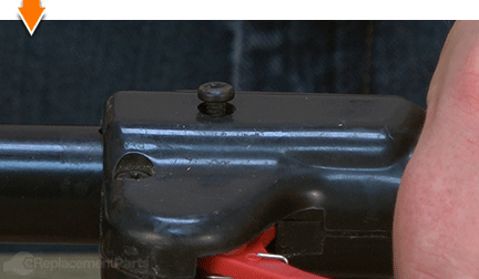
Secure the anti-rotation screw.

You don't have to leverage your savings to level your lawns. As you just learned, repairing your own equipment is easy when you follow our step-by-step guides. Not only did you restore trimmer functionality at a fraction of the cost of replacement; you have taken the edge off of future repairs, wherever you may find them.


