Why Read This Article?
Finish Nailer Repair - Replacing the Driver Guide (Ridgid Part # 79004001022)
Article Breakdown
Finish Nailer Repair - Replacing the Driver Guide (Ridgid Part # 79004001022)
Tools & Materials
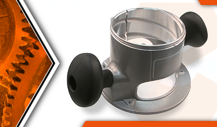

Running out of patience with a run-down router? It's time to face the fix. Whether you are a master carpenter or a weekend woodworker, eReplacementParts.com provides the parts, procedures and facts you need to fearlessly fix what fails you.
The base housing assembly consists of the cast base and the two side handles. This is the part you want if your router base has become cracked or damaged (usually as a result of dropping the router). Replacing the base housing assembly is easy to do.
This article provides step-by-step instructions for removing and installing the base housing assembly on a Porter Cable 690 series router.
Let's get started.
 REMOVING THE BASE HOUSING [top]
1. Remove the base housing.
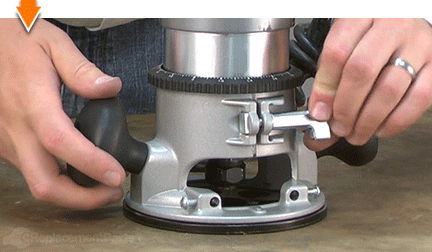
Rotate the knob to loosen the base clamp assembly.
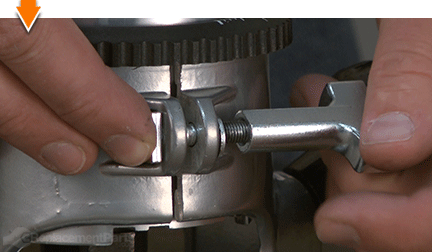
While holding the base housing assembly, rotate the motor unit COUNTERCLOCKWISE until the pins in the motor housing disengage from the grooves in the base.
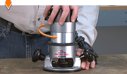
Lift the power unit out of the base assembly.
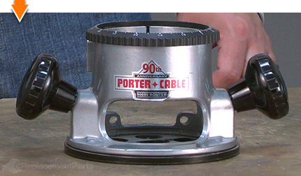
2. Remove the clamp components.
Loosen and remove the clamp knob from the housing.
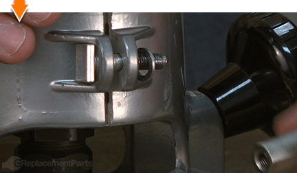
Remove the clamp screw and washer from the housing.
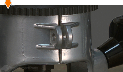
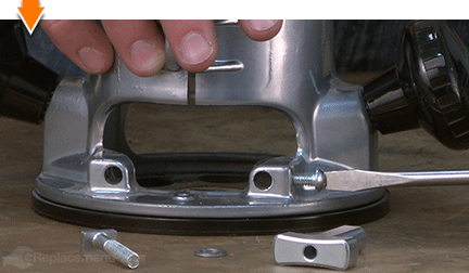
3. Remove the edge-guide screws (not all models include these screws).
Remove the (2) edge-guide screws from the housing.
4. Remove the sub-base.
Remove the (3) screws from the sub-base.
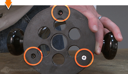
Remove the sub-base from the housing.
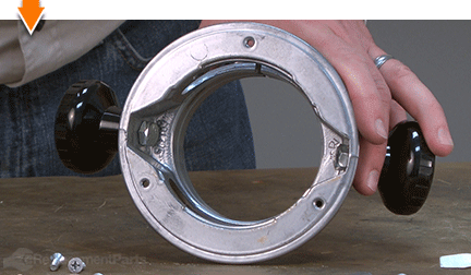
5. Remove the depth adjustment ring.
Pry/lift the depth adjustment ring away from the housing.
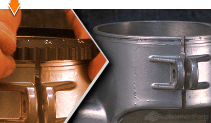
Locate the (3) depth adjustment springs. These "springs" (which are actually more like three short segments of metal wire) will likely fall away from the housing when the depth adjustment ring is removed. They may also remain fixed within the adjustment ring.
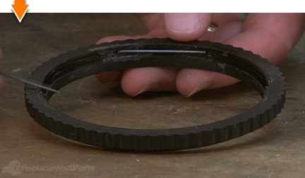
ASSEMBLING THE NEW BASE HOUSING [top] 6. Install the side handles.
Install the side handle to the base housing with either of the (supplied) screws.
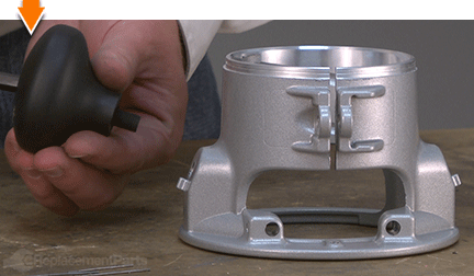
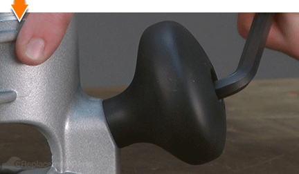
Secure the side handle to the base using an 8 millimeter hex wrench.
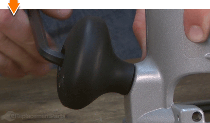
Repeat this step to install the second side handle.
7. Install the clamp assembly.
Install the clamp screw through the tabs in the new housing. Note that the head of the clamp screw is wider on one side. The wide side should be positioned against the router.
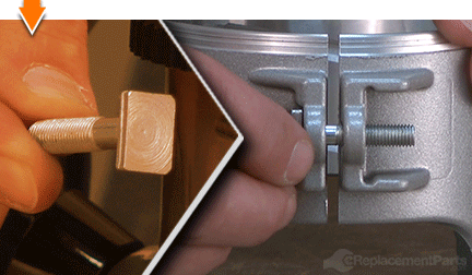
Slide the washer onto the clamp screw.
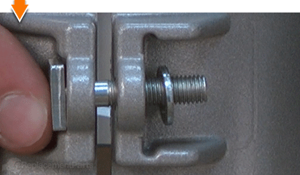
Install (but do not fully tighten) the clamp knob onto the clamp screw.
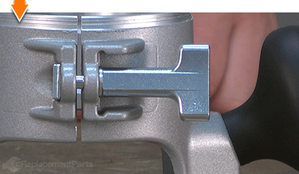
8. Install the edge-guide screws.
Install the (2) edge-guide screws onto the base housing (if applicable).
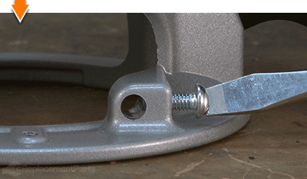
9. Install the sub-base.
Place the sub-base onto the base housing; align the mounting holes.
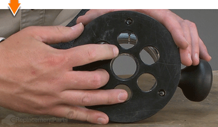
Secure the sub-base to the housing with the (3) screws.
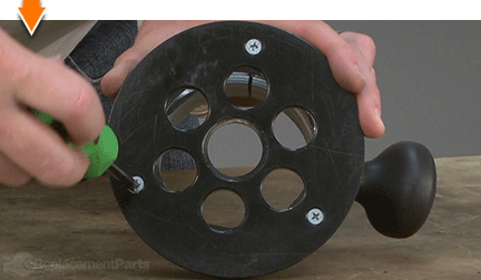
10. Install the depth adjustment ring.
Install the (3) springs into the grooves within the depth adjustment ring. The springs should be evenly spaced within the ring.
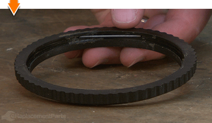
Install the depth adjustment ring onto the base housing. The springs within the ring should "snap" into the metal groove around the base housing. Start with one spring; then work your way around the ring until all three springs engage the groove in the housing.
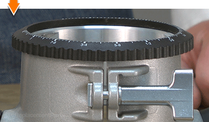
REASSEMBLING THE UNIT [top] 11. Reconnect the motor to the base housing.
Set the motor unit into the base.
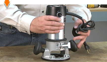
Rotate the motor unit CLOCKWISE until the upper guide pins on the motor are set in the groove of the base.
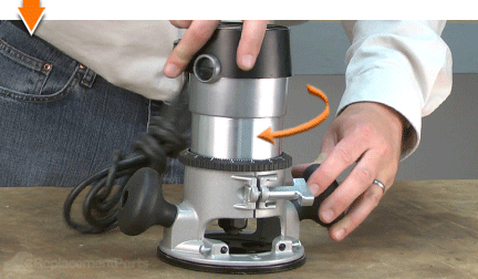
Tighten the clamp to secure the unit.

Dovetails. Rabbets. Dados. Grooves: The possibilities are as priceless as machines that create them. But you don't have to be a carpenter to cut out the middle-man. Repairing your own powered equipment is easy and economical when you follow our step-by-step guides. Not only did you restore your router at a fraction of the cost of replacement; you built on your ability to face the next fix, whatever it may be.


