Why Read This Article?
Finish Nailer Repair - Replacing the Driver Guide (Ridgid Part # 79004001022)
Article Breakdown
Finish Nailer Repair - Replacing the Driver Guide (Ridgid Part # 79004001022)
Tools & Materials
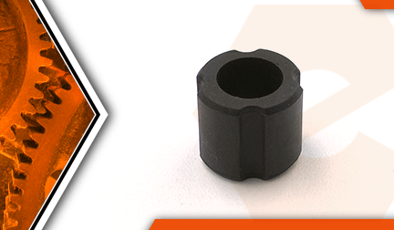

String trimmer out of whack? It's time to face the fix. Whether you are a legendary landscaper or a weekend weed whacker, eReplacementParts.com provides the parts, procedures and facts you need to fearlessly fix what fails you.
Stoppers are flexible rubber inserts located within each end of the trimmer's main pipe. Their function is to prevent the cable shaft liner from drifting up and down (and vibrating) within the pipe. Because they are made of rubber, stoppers will eventually harden and crack.
If your trimmer vibrates excessively during use, inspecting the stoppers is a simple and sensible first step that can save you a significant amount of time and money. Replacing the stoppers is easy to do.
This article provides step-by-step instructions for removing and installing cable liner stoppers on an Echo trimmer. (The model shown in this tutorial is the Echo SRM-225.)
Let's get started.
 REMOVING THE STOPPER(s) [top]
1. Remove the control handle assembly.
Remove the (4) screws from the cover of the control handle assembly.
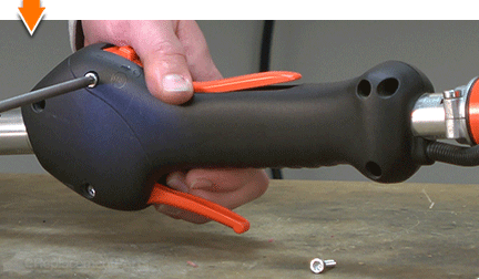
Remove the cover from the control handle assembly.
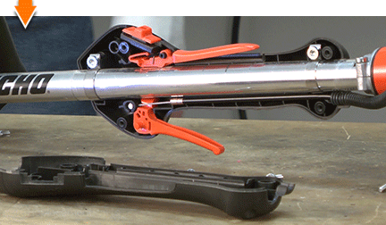
Remove the (2) screws from the clamps inside the control handle.
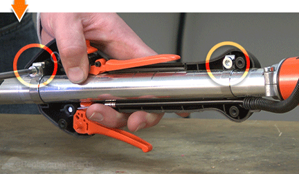
Remove the control handle assembly.
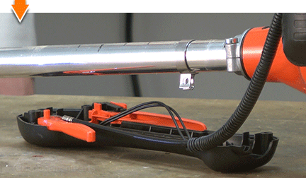
2. Remove the gear housing and the shield assembly.
Remove the single alignment screw from the top of the gear housing.
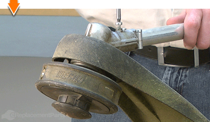
Loosen the (2) clamp screws.
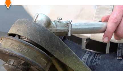
Twist the gear housing slightly while pulling the assembly away from the main pipe.
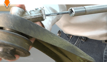
Remove the gear housing and the shield assembly from the unit.
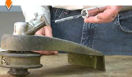
3. Remove the main pipe from the engine.
Loosen the (2) clamp screws.
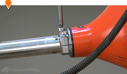
Slide the main pipe away from the engine.
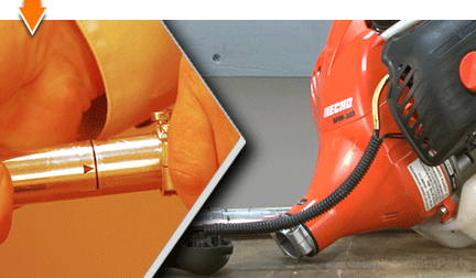
4. Remove the stoppers.
Use long-nosed pliers to remove the stopper(s) from the end(s) of the main pipe.
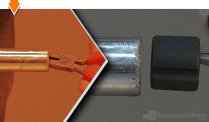
INSTALLING THE NEW STOPPER(s) [top] 5. Install the stoppers.
Install the new stopper(s) into the end(s) of the main pipe.
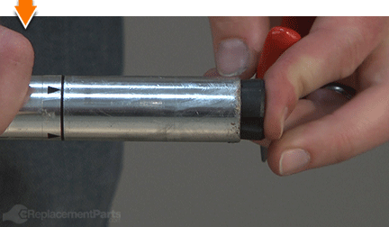
Push each stopper securely into the main pipe; the stopper(s) will contact the shaft liner when installed deeply enough.
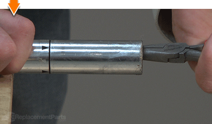
REASSEMBLING THE UNIT [top] 6. Reinstall the main pipe into the engine assembly.
Slide the main pipe (and drive shaft) into the engine assembly until the indicator marks on the pipe align with the holders.
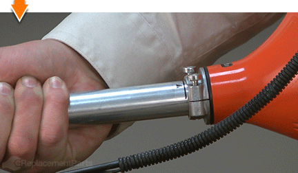
Secure the engine to the main pipe with the (2) screws.
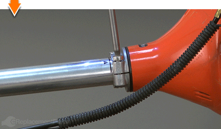
7. Reinstall the gear housing and shield assembly.
Slide the gear housing and shield assembly onto the end of the main pipe.
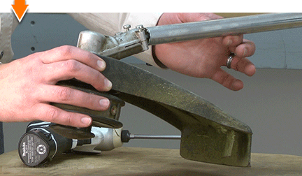
Rotate to gear housing assembly (if necessary) until the drive shaft engages the gearbox.
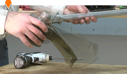
Align the hole in the top of the gear housing with the hole in the top of the main pipe.
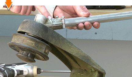
Install and secure the single alignment screw.
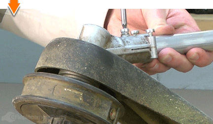
Secure the (2) clamp screws.
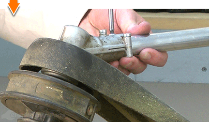
8. Reinstall the control handle assembly.
Use a screwdriver to tuck the ignition wires into the channels along the inside of the control handle.
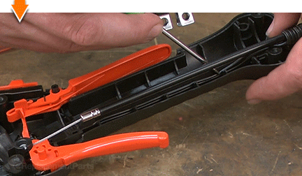
Align the throttle cable with the grooves along the control handle (above the ignition wires).
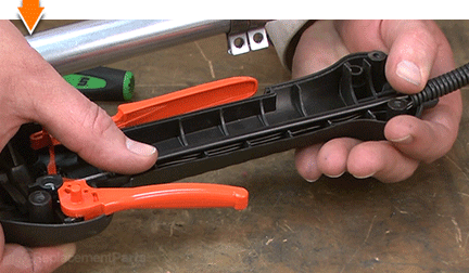
Position the control handle assembly on the main pipe.
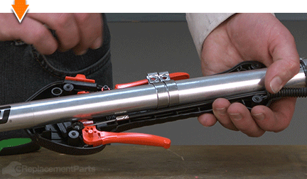
Align the metal ring clamps with the slots in the control handle assembly.
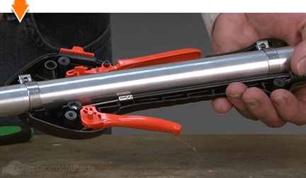
Install (but do not fully tighten) the (2) screws into the ring clamps.
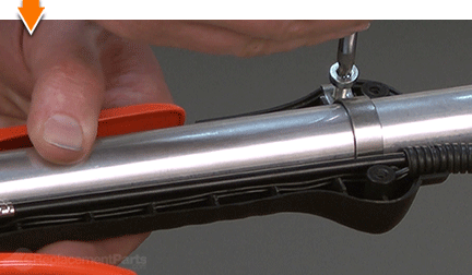
Rotate the control handle assembly into alignment with the engine and the front handle.
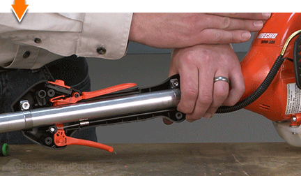
Fully tighten the screws in the ring clamps to secure the control handle assembly.
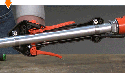
9. Reinstall the cover.
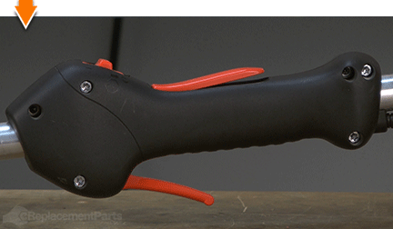
Install the cover onto the control handle assembly.
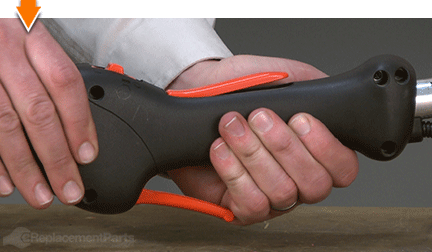
Secure the cover with the (4) screws.

You don't have to leverage your savings to level your lawns. As you just learned, repairing your own equipment is easy when you follow our step-by-step guides. Not only did you restore trimmer functionality at a fraction of the cost of replacement; you have taken the edge off of future repairs, wherever you may find them.


