Why Read This Article?
Finish Nailer Repair - Replacing the Driver Guide (Ridgid Part # 79004001022)
Article Breakdown
Finish Nailer Repair - Replacing the Driver Guide (Ridgid Part # 79004001022)
Tools & Materials
- a hammer
- a flat-head screwdriver
Safety Guidelines
- Always remember to disconnect a tool from its power source before dismantling it or performing repairs.
- A clean workspace can minimize the potential for accidents and prevents dismantled tools from being exposed to dirt.
 *These instructions apply only to model numbers 6519-22, 6520-21, 6521-21, 6523-21 and 6536-21 Sawzalls with QUIK-LOK® Blade Clamps.
Tools needed to remove the blade clamp assembly are:
- a hammer, and
- a flat-head screwdriver.
REMOVING THE QUIK-LOK BLADE CLAMP
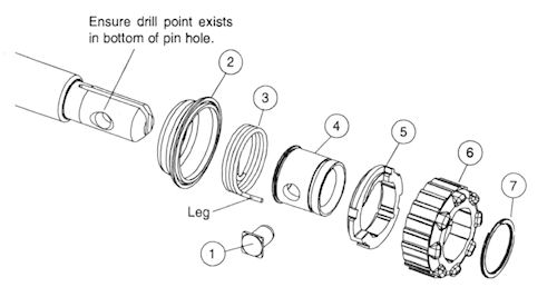
1. Remove external retaining ring (7) and pull front cam (6) off.
2. Pull lock pin (1) out and remove remainder of parts.
1. Coat new lock pin with powdered graphite.
2. Hold tool in a vertical position.
3. Place spring cover (2) onto spindle.
4. Slide torsion spring (3) onto spindle with spring leg 90 degrees counterclockwise from the hole in the spindle.
5. Slide sleeve (4) onto spindle aligning hole on sleeve with hole in spindle.
6. Slide rear cam (5) over sleeve until it bottoms on sleeve shoulder, ensure spring leg inserts into hole in rear cam.
7. Rotate rear cam counterclockwise until there is a clearance for lock pin (1) to be inserted into sleeve/spindle holes. Insert lock pin.
8. Align front cam (6) inner ribs with rear cam outer slots and slide front cam onto sleeve until it bottoms. Retaining ring groove should be completely visible.
9. Attach retaining ring (7) by separating coils and inserting end of ring into groove, then wind remainder of ring into groove. Ensure ring is seated in groove.
10. Blade clamp should rotate freely. During normal usage, debris may prevent blade clamp from rotating freely.
 [Back to top]
What we're about.


