Why Read This Article?
Finish Nailer Repair - Replacing the Driver Guide (Ridgid Part # 79004001022)
Article Breakdown
Finish Nailer Repair - Replacing the Driver Guide (Ridgid Part # 79004001022)
Tools & Materials
 THE FACTS | THE FIX | THE FINISH
If broken drills and service bills are boring holes in your budget; it's time to face the fix. Whether you are a master craftsman or an occasional drill-seeker, eReplacementparts.com provides the parts, procedures and facts you need to fearlessly fix what fails you.
The gear case assembly consists of the transmission and the clutch. Problems with either of these may require you to replace the entire assembly. Common symptoms can include loss of hammer functionality, inability to select gears, or clutch slippage at higher torque settings. If your hammer drill is at a standstill and you're certain it's the gear case, this article will guide you through the steps required to successfully replace the assembly.
THE FACTS | THE FIX | THE FINISH
REMOVING THE GEAR CASE ASSEMBLY [top]
1. Remove the battery.
THE FACTS | THE FIX | THE FINISH
If broken drills and service bills are boring holes in your budget; it's time to face the fix. Whether you are a master craftsman or an occasional drill-seeker, eReplacementparts.com provides the parts, procedures and facts you need to fearlessly fix what fails you.
The gear case assembly consists of the transmission and the clutch. Problems with either of these may require you to replace the entire assembly. Common symptoms can include loss of hammer functionality, inability to select gears, or clutch slippage at higher torque settings. If your hammer drill is at a standstill and you're certain it's the gear case, this article will guide you through the steps required to successfully replace the assembly.
THE FACTS | THE FIX | THE FINISH
REMOVING THE GEAR CASE ASSEMBLY [top]
1. Remove the battery.
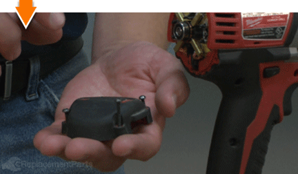
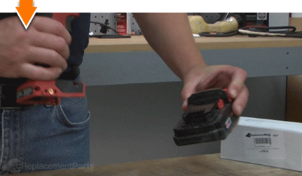 2. Remove the end cap.
Extract the four retaining screws.
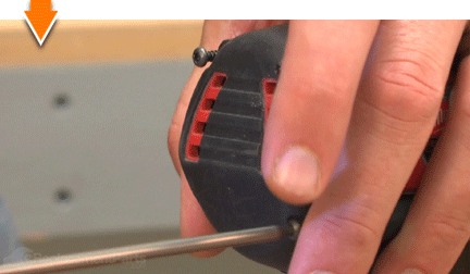
Remove the end cap. Make note of the position of the screws within the cover (there are two different sizes).
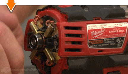
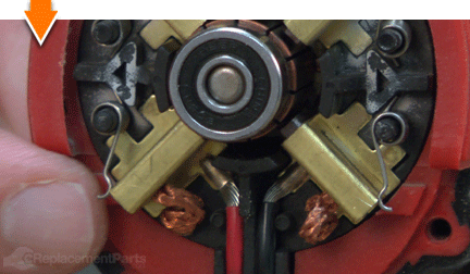
 3. Disengage the brush springs.
Use a small screwdriver or pick to disengage the four brush springs from the brushes on the card assembly. This relieves pressure on the armature, allowing it to slide freely from the assembly.
 4. Remove the chuck.
Rotate the chuck until it is fully open.
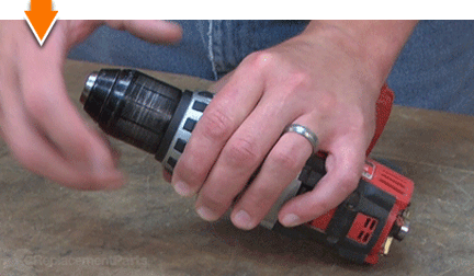
Extract the chuck retaining screw using a Phillip's screwdriver. This screw contains reverse-threads (requiring clockwise rotation to remove).
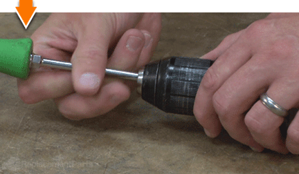
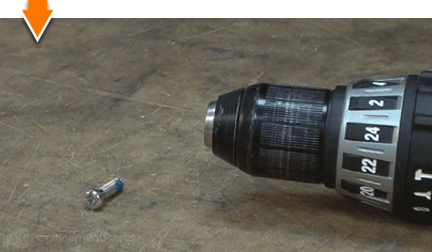
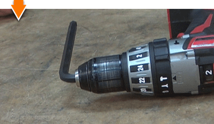
Insert the short end of a large Allen wrench (as large as the opening will accommodate) into the chuck; tighten securely.
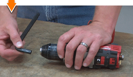
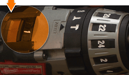
Switch the transmission to the lowest setting.
Position the drill on a surface that allows the chuck (and Allen wrench) to overhang the edge.
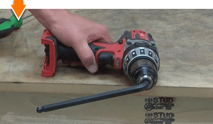
SPECIFIX: The next step involves striking the Allen wrench with a rubber mallet to loosen the chuck assembly. Before proceeding to the next step, make certain that the drill is positioned to ensure that the blow from the mallet rotates the assembly in a counter-clockwise motion. Striking the wrench in the wrong direction will tighten (and possibly damage) the chuck assembly.
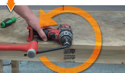
While securely holding the drill against the work surface, strike the exposed end of the Allen wrench with a rubber mallet. This should loosen the chuck assembly.
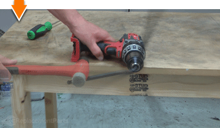
Continue to rotate (unscrew) the chuck assembly (by hand) until it disengages the spindle.
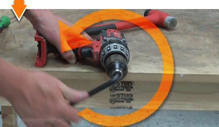
Remove the chuck assembly.
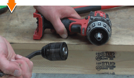 5. Remove the housing case.
Extract the retaining screws from the top half of the housing case.
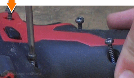
Use a screwdriver to carefully disengage the edges of the case.
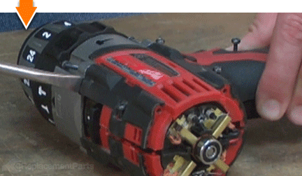
Remove the top half of the case.
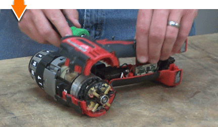 6. Remove the gear case assembly.
Remove the remaining screws from (the face of) the gear case assembly.
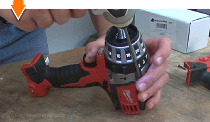
Lift the gear case assembly out of the housing case. Typically, the motor will remain attached to the gear case as it is lifted from the housing.
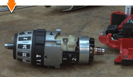
SPECIFIX: Occasionally, the motor will remain fixed within the drill housing as the gear case assembly is lifted from the unit. In such cases, the motor will need to be removed from the housing and set aside for installation with the new gear case.
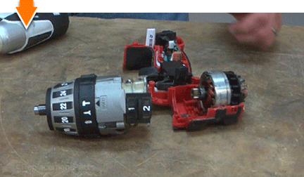
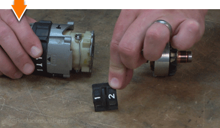
Separate the motor from the gear case assembly (or remove it from the housing).
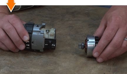
Remove the gear selector switch.
 INSTALLING THE NEW GEAR CASE ASSEMBLY [top]
7. Install the new gear case assembly.
Reattach the motor to the new gear case assembly (insert the gear-end of the motor into the transmission).
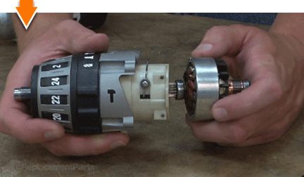
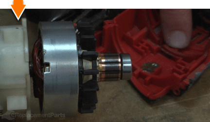
Install the gear case/motor assembly into the housing. Note that the motor contains notches on both sides of the field. These notches must align with the tabs on the plastic housing.
 REASSEMBLING THE UNIT [top]
8. Reinstall the gear selector switch.
Install the gear selector switch, ensuring that the notch on the switch aligns with the wire on the gear case assembly.
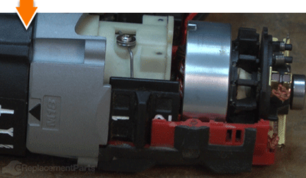
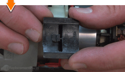 9. Reinstall the housing case.
Inspect the wiring within housing. Use a small screwdriver to reseat any wires that may have become misaligned during disassembly.
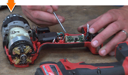
Reinstall the top half of the housing case; tap lightly on the case to snap the two halves together.
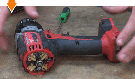
Secure the housing case with the screws.
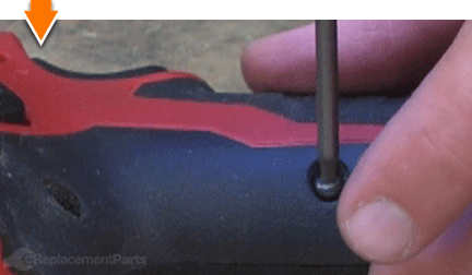
Secure the gear case assembly to the housing with the screws.
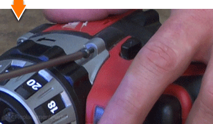 10. Re-engage the brush springs.
Use a small screwdriver or pick to re-engage the four brush springs.
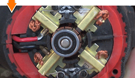 11. Reinstall the end cap.
Reinstall the end cap.
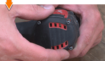
Secure the end cap to the unit with the screws.
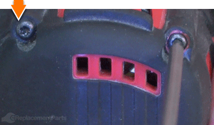 12. Reinstall the chuck.
Install the chuck to the gear spindle; hand-tighten only (rotating in a clockwise direction).
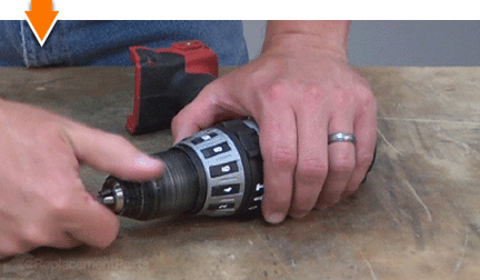
Open the chuck to its widest position.
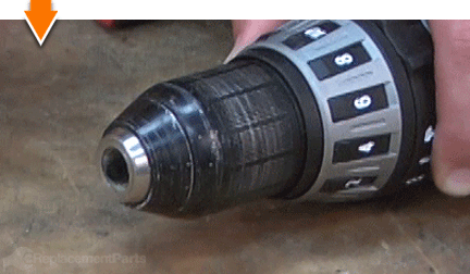
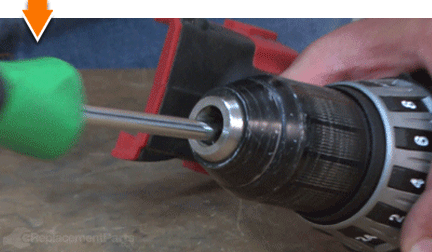
Secure the chuck with the retaining screw. Remember, this screw contains reverse-threads (requiring counter-clockwise rotation to tighten).
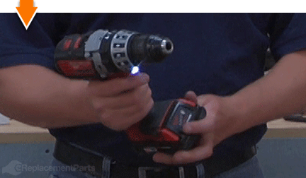
 13. Replace the battery.
 THE FACTS | THE FIX | THE FINISH
As you just learned, fixing things yourself means more drilling with less billing. Hopefully, this article has helped restore your ability to drill holes without replacing your whole drill. But that's just the tip of the bit. Our Follow-and-Fix Field Guides can help expand your skills far beyond drills; empowering you to face power tool problems as they arise, and to fearlessly fix whatever fails you.
Find your next fix here.
[top]


