


Why Read This Article?
Finish Nailer Repair - Replacing the Driver Guide (Ridgid Part # 79004001022)
Article Breakdown
Finish Nailer Repair - Replacing the Driver Guide (Ridgid Part # 79004001022)
Video
Tools & Materials
Safety Guidelines
 THE FACTS | THE FIX | THE FINISH
If shortened straws and faulty saws have left you powerless to cut construction costs, it's time to face the fix. Whether building in your own backyard or building on your business, eReplacementparts.com provides the parts, procedures and facts you need to cut out the middle-man and fearlessly fix what fails you.
Aside from battery burnout, few things will silence a reciprocating saw more surely than a glitch in the switch. When this happens, you'll begin to notice symptoms such as intermittent stalling, finicky functionality, and eventually a complete inability to activate the saw. If your saw has seen better days, and you're certain it's the switch, this article will guide you through the steps necessary to successfully make the swap.
THE FACTS | THE FIX | THE FINISH
REMOVING THE SWITCH [top]
THE FACTS | THE FIX | THE FINISH
If shortened straws and faulty saws have left you powerless to cut construction costs, it's time to face the fix. Whether building in your own backyard or building on your business, eReplacementparts.com provides the parts, procedures and facts you need to cut out the middle-man and fearlessly fix what fails you.
Aside from battery burnout, few things will silence a reciprocating saw more surely than a glitch in the switch. When this happens, you'll begin to notice symptoms such as intermittent stalling, finicky functionality, and eventually a complete inability to activate the saw. If your saw has seen better days, and you're certain it's the switch, this article will guide you through the steps necessary to successfully make the swap.
THE FACTS | THE FIX | THE FINISH
REMOVING THE SWITCH [top]
SPECIFIX: This model contains a light-emitting diode in the front portion of the saw. Because the LED is attached directly to the switch, this repair involves disassembling both sections of the saw housing (front and rear).
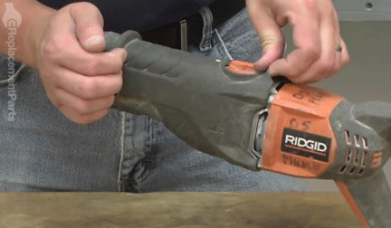
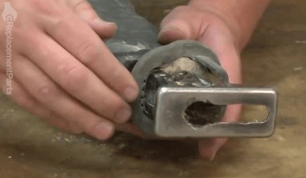
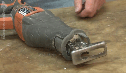
1. Remove the shoe and the shoe release lever.
Rotate/raise the shoe release lever to the open position.
Slide the shoe forward to remove it from the gear case housing assembly.
Use a screwdriver to gently pry the shoe release lever away from the gear case housing on both sides of the saw.
Remove the shoe release lever.
Remove the shoe pin.
2. Remove the rubber boot.
Lift the top-rear portion of the rubber boot until it clears the orange orbital button (on the top of the saw).
Pull from the front (blade-end) of the rubber boot to remove it from the housing.
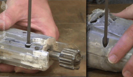
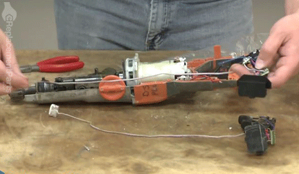
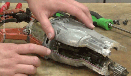
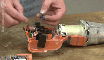
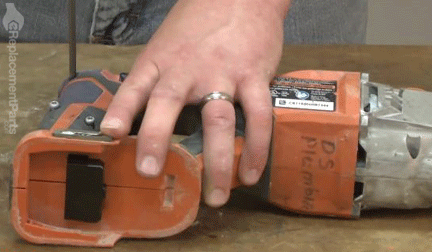
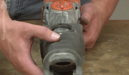
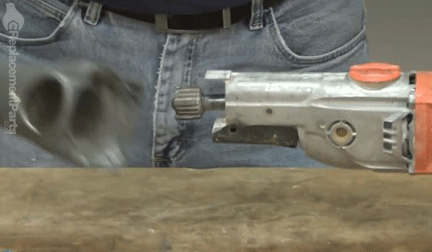 3. Remove the plastic housing.
Remove the (vertical) retaining screws from the plastic housing.
Remove the (horizontal) retaining screws from the housing.
Use a screwdriver to gently pry apart the two halves of the housing.
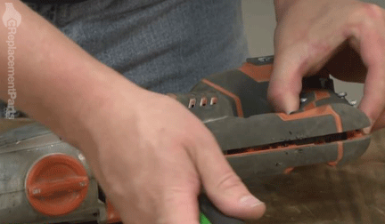
Remove the plastic housing from the saw handle.
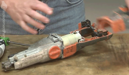
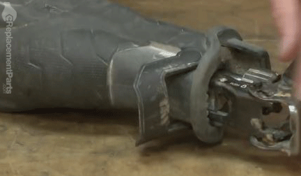
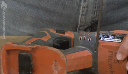
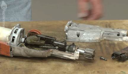
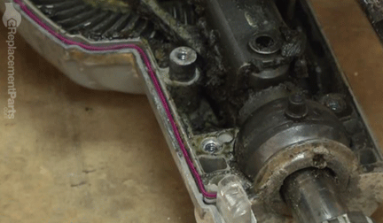
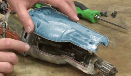
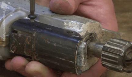
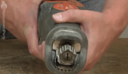
4. Remove the metal gear case housing cover.
SPECIFIX: Although visible and accessible at this point, the switch cannot be entirely removed from this specific model without removing the attached LED assembly (which is mounted in the front portion the saw). The LED assembly receives power from a wire that runs through the entire unit; therefore, removal of the gear case housing is required to remove and replace the switch.
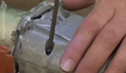
Extract the screw from the shoe retainer.
Remove the shoe retainer from the gear case housing.
Remove the retaining screws from the gear case housing cover.
Remove the gear case housing cover from the unit.
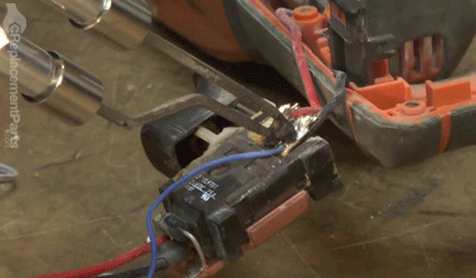
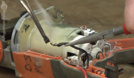
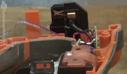
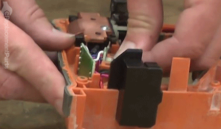
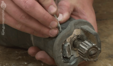
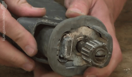
5. Remove LED and switch assembly from the saw housing.
Remove the LED assembly from the housing.
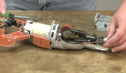
Carefully lift and remove the LED wires from the recess channels along the perimeter of the unit.
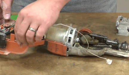
Remove the circuit board and the switch assembly from the handle housing.
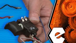
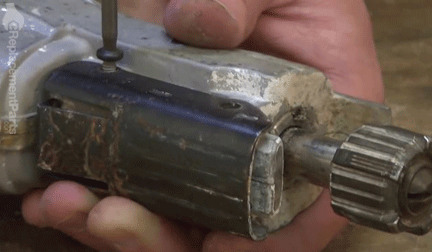
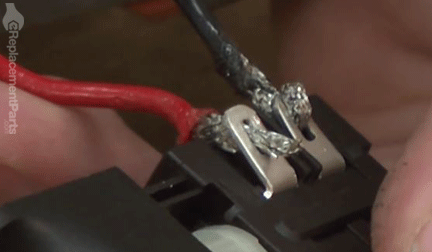
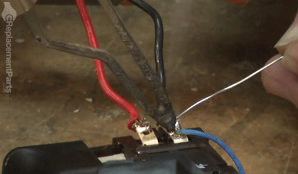
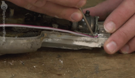
6. De-solder the wire connections from the switch.
SPECIFIX: Safety glasses are recommended when working with solder. Before de-soldering, make note of the configuration of the existing wires to ensure accurate reassembly.
 Black / Blue Connection:
Use a soldering gun to heat the connection.
Use a solder-sucker to remove the molten solder.
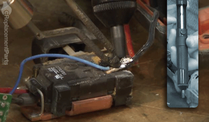
Continue applying heat to the connection while using long-nosed pliers to detach the wires from the terminal.
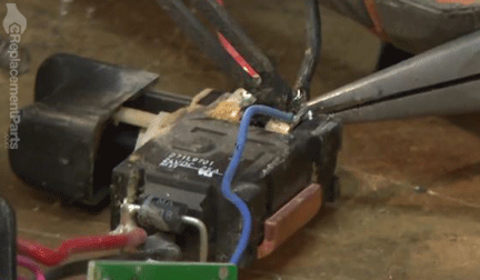
Once removed, apply heat to the exposed end of the wire to evenly distribute any remaining solder and prepare the wire for reattachment.
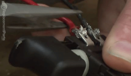
 Red Connection:
Repeat the previous steps to de-solder and remove the red wire from the switch assembly.
INSTALLING THE NEW SWITCH [top]
FIX TRIX: Prior to installation, closely compare the old and new switches to identify any wiring inconsistencies and to configure the new wires for installation.
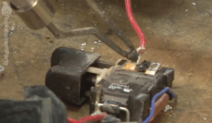
 7. Solder the wires to the switch terminals.
Insert the red and black wires through the corresponding eyelets on the switch terminal.
Using long-nosed pliers, bend the tips of each of the wires backwards to prevent them from slipping out of the eyelets.
Insert the LED supply-wire (blue) into the eyelet containing the black wire; bend or crimp the wires on the reverse side of the connection to prevent slippage.
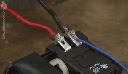
Apply paste flux to each of the connections.
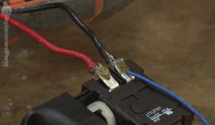
Solder the wires to the terminals of the new switch.
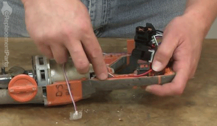
REASSEMBLING THE UNIT [top] 8. Install the switch assembly into the handle housing.
Insert the new switch assembly into the housing recess.
Carefully tuck the switch-side wires into the channels along the perimeter of the handle housing. (Use a small screwdriver as necessary.)
9. Install the LED assembly.
FIX TRIX: When routing the LED supply wires, begin at the LED mounting point and work back toward the switch. This will enable you to conceal any excess wire in the handle.
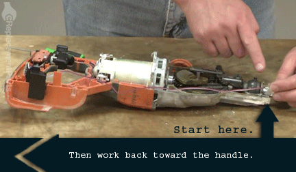
Install the LED assembly into the gear case housing recess.
Carefully tuck the LED wires into the channels along the perimeter of the gear case housing and the handle housing.
 10. Reinstall the gear case housing cover.
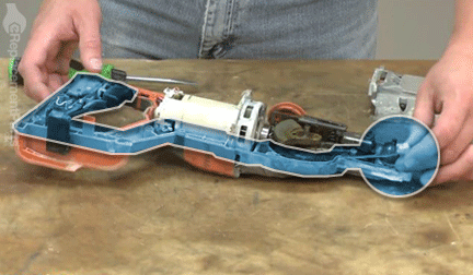
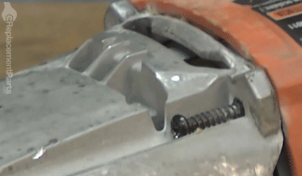
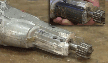
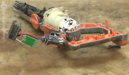
SPECIFIX: Replacing the metal housing cover requires patience and precision. As the two halves are joined, you must ensure that the front connector pins (2) align with the corresponding recesses in the cover plate, and that the motor shaft aligns with the bearing in the top plate. You must also ensure that the compression spring located in the top of the saw does not slide out of position during installation.
The following illustrations will help familiarize you with the locations of these critical components:
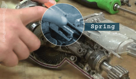
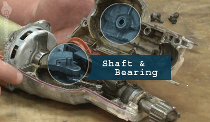
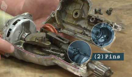
Reinstall the top metal cover, ensuring alignment of the four components detailed above.
Secure the metal case with the screws.
 11. Reinstall the shoe retainer.
Reinstall and secure the shoe retainer.
 12. Reinstall the LED switch.
Insert the retaining spring into the LED switch.
Install the LED switch assembly into the recess in the handle.
 13. Reinstall the handle housing.
Reinstall the handle housing.

Securely the handle housing with the screws.
 14. Reinstall the rubber boot.
Slide the rubber boot over the gear case housing.
Ensure that the boot is properly seated over the orbital button.
 15. Reinstall the shoe release lever.
Insert the shoe retainer pin.
Reinstall the shoe release lever. When properly seated, the lever should be able rotate smoothly between the open and locked positions.
 16. Reinstall the shoe.
With the shoe release lever in the open position, slide the shoe into the retaining bracket at the end of the saw.
Rotate the shoe lock lever to the locked position to secure the shoe.
 THE FACTS | THE FIX | THE FINISH
You can't cut corners when it comes to construction, but you can cut costs. Keeping the tools of your trade in razor-sharp condition allows you trim unnecessary costs, while building more savings into your own bottom line. Not only did you restore reciprocation at a sliver of the cost of replacement; you sharpened your skills, along with your ability to fearlessly face the next fix.
Find your next fix here.
[top]
THE FACTS | THE FIX | THE FINISH
You can't cut corners when it comes to construction, but you can cut costs. Keeping the tools of your trade in razor-sharp condition allows you trim unnecessary costs, while building more savings into your own bottom line. Not only did you restore reciprocation at a sliver of the cost of replacement; you sharpened your skills, along with your ability to fearlessly face the next fix.
Find your next fix here.
[top]
